
![[Grasshopper] How to use Populate Geometry to create random points on and in geometry](https://iarchway.com/wp-content/uploads/2025/10/Populate-Geometry.png)
This article explains how to use Populate Geometry to create random points on and in geometry.
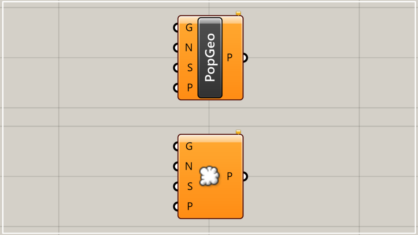
On the Grasshopper, it is represented by either of the two above.
Creating Random Points on and in Geometry
Populate Geometry allows you to create random points on and in geometry.
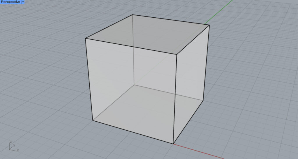
We will first use this solid model on Rhino.
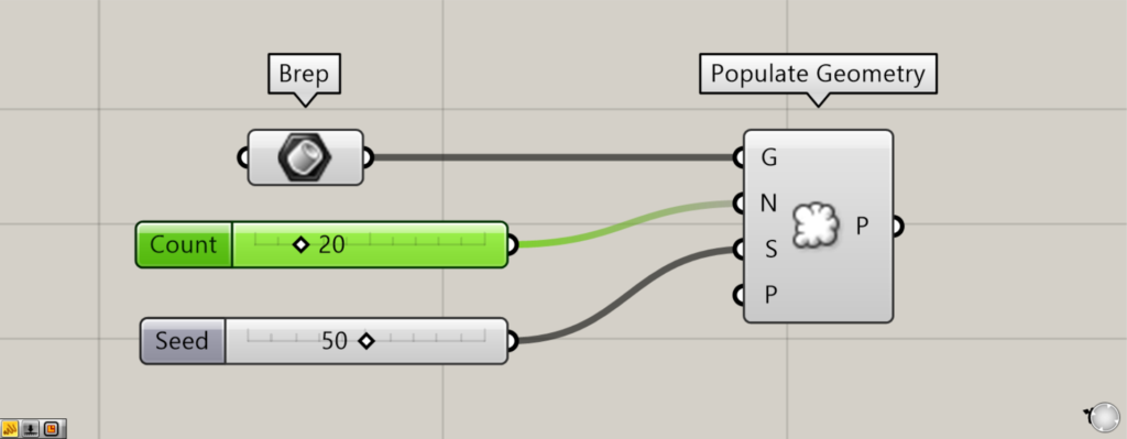
Components used: ①Brep ②Populate Geometry

The solid on Rhino is set in a Brep.
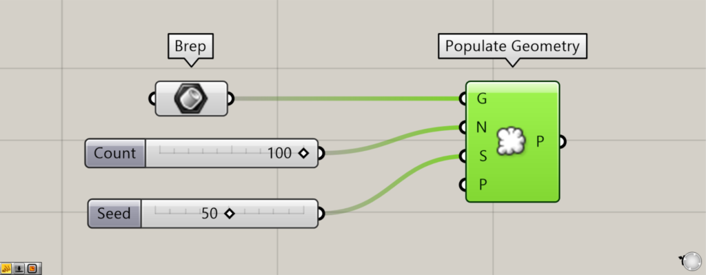
Then, connect the Prep to the Populate Geometry(G).
Enter the number of points to be generated in the Populate Geometry(N).
In this case, enter 100.
Input the seed value of the randomness to the Populate Geometry(S).
This time, 50 is input.
As an example, if we connect the Number Slider, which can be changed from 1~100, to the Populate Geometry(S), we can create 100 different patterns.
Then, as shown in the image above, random points are created on and in the model.
In this case, 100 points are randomly created.
We changed the value of the Populate Geometry(N) from 100 to 20.
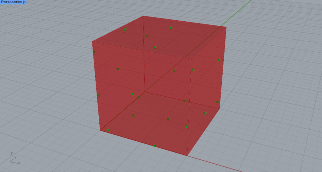
As you can see, the number of generated points is reduced.
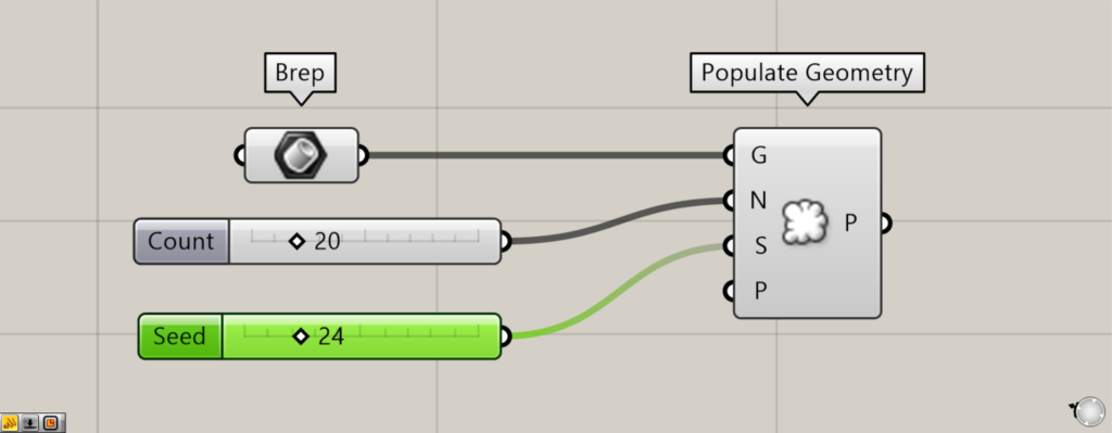
Next, we changed the value of the Populate Geometry(S) from 50 to 24.

As you can see, the randomness changed and the arrangement of the points changed.
In this way, the number of points and the randomness can be freely adjusted.
Various types of models
Populate Geometry can be used with various types of models.
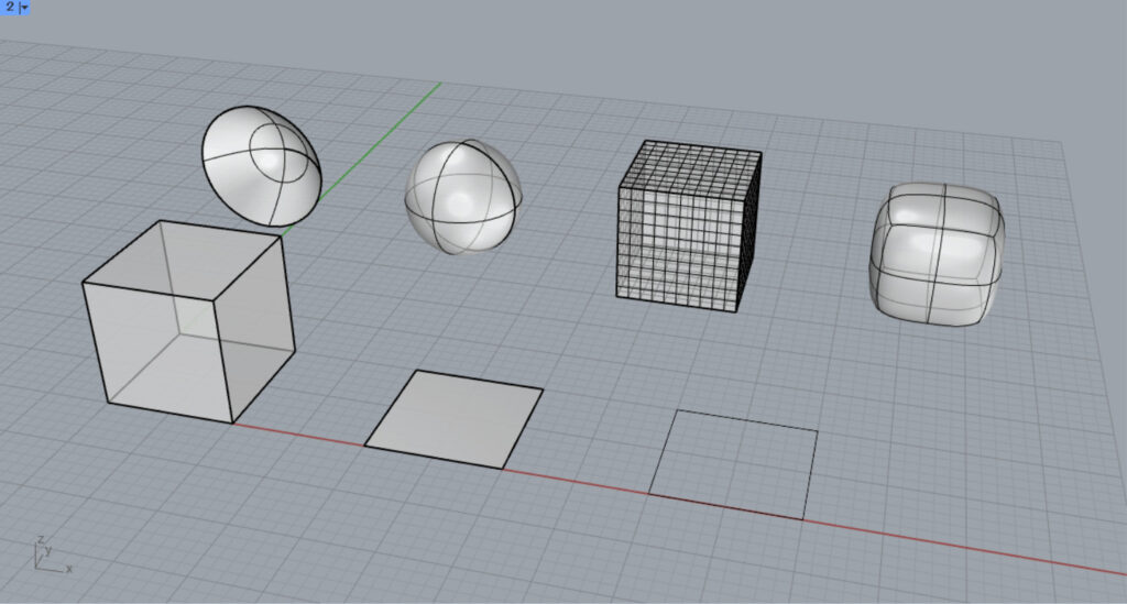
Various types of models are available.
The types include solids (polysurfaces), surfaces, lines, meshes, and SubD.
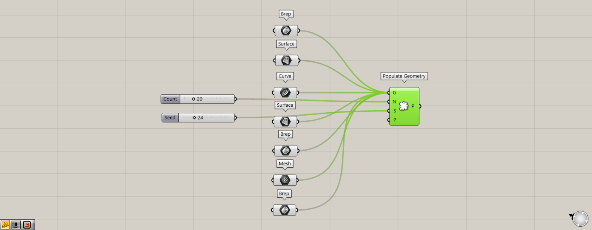
Components used: (1) Brep (2) Surface (3) Curve (4) Mesh (5) Populate Geometry
Let’s connect all of them to Populate Geometry.
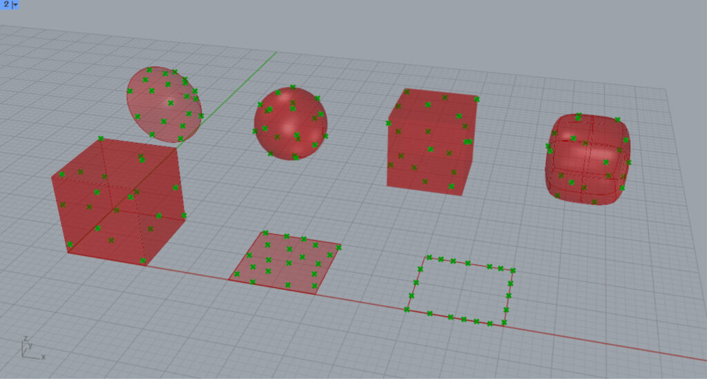
As you can see, Populate Geometry could be used with various types of models.
In the case of this three-dimensional solid, polysurface, mesh, SunD, etc., you can see that points are created on and in the model.
In the case of a 2D surface, a point is created on the surface.
In the case of a line, a point is created on the line.
P
Specifying an existing point in the Populate Geometry(P) will prevent new points from being placed around that point.
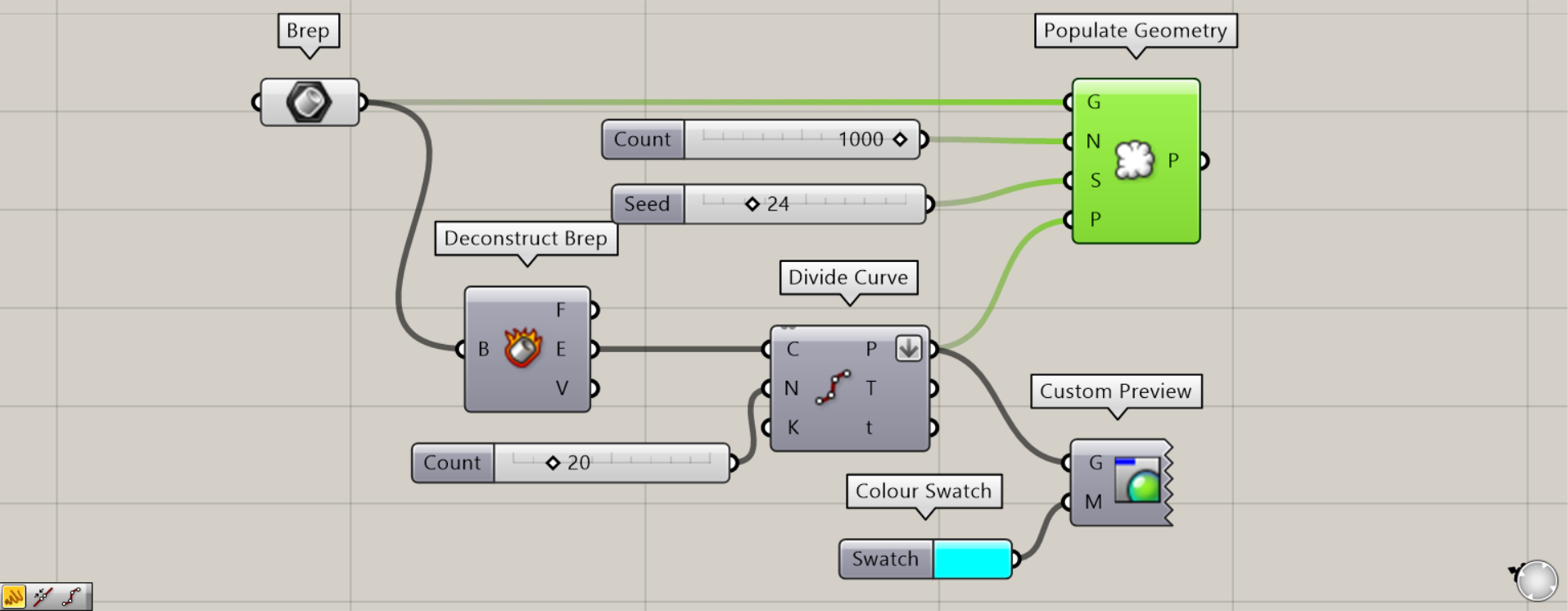
Components used: (1) Brep (2) Deconstruct Brep (3) Divide Curve (4) Colour Swatch (5) Custom Preview (6) Populate Geometry
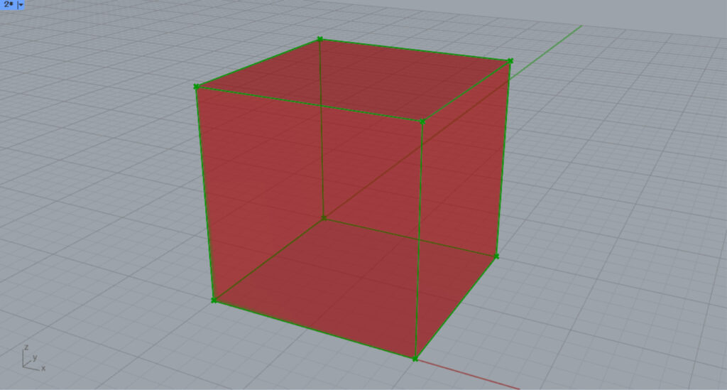
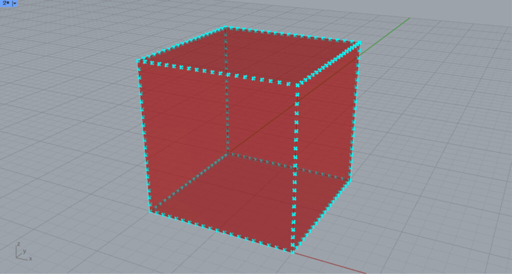
This time, we will create and connect the points that divide the cube’s border at equal intervals to the Populate Geometry(P).
First, connect Brep to Deconstruct Brep.
Then, the cube is decomposed and the border is obtained from the Deconstruct Brep(E).
Then, connect the Construct Brep(E) to the Divide Curve(C).
Then, input the number of line divisions to the Deconstruct Brep(N).
Since 20 is entered this time, create a point at the position where the line is equally divided into 20.
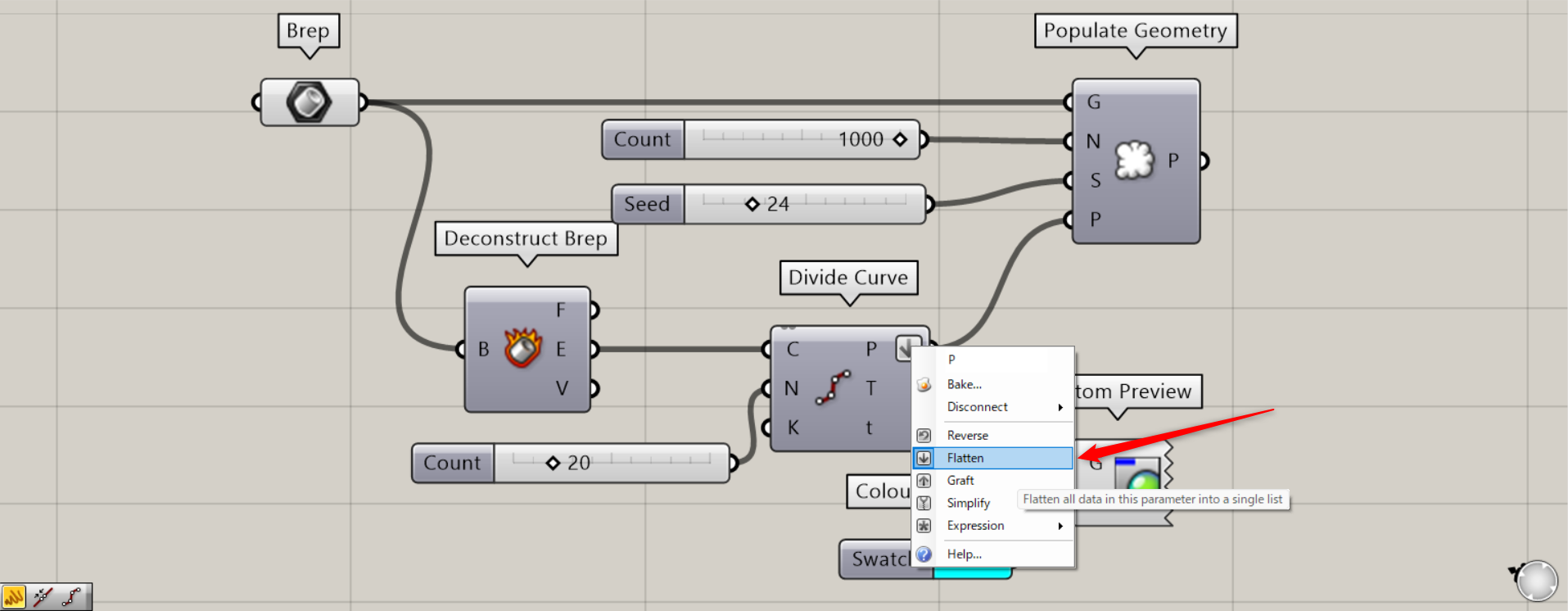
At this point, right click on the Divide Curve(P) and set it to Flatten.
Also, this time, to make it easier to see, we used Colour Swatch and Custom Preview to make these points light blue.
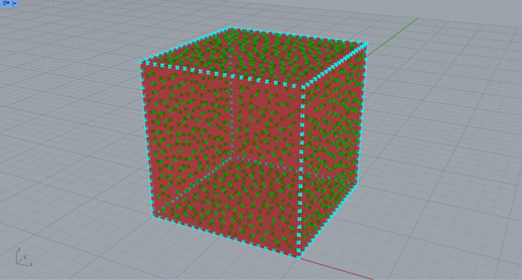
Then, connect the Divide Curve(P) to the Populate Geometry(P).
This time, the number of points at the Populate Geometry(N) is set to 1000.
This prevents new points from being placed around the point at the border position.
This is how the points are generated when the P is not specified.
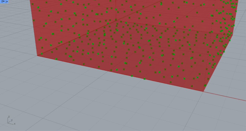
If you zoom in, you can see that points are generated near the border when the P is not specified.
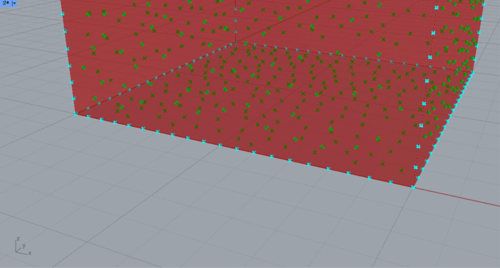
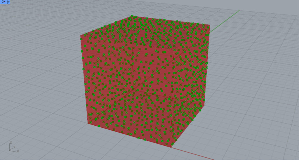
If points on the border are specified for the P, you can see that a point is no longer created near the cube’s border.
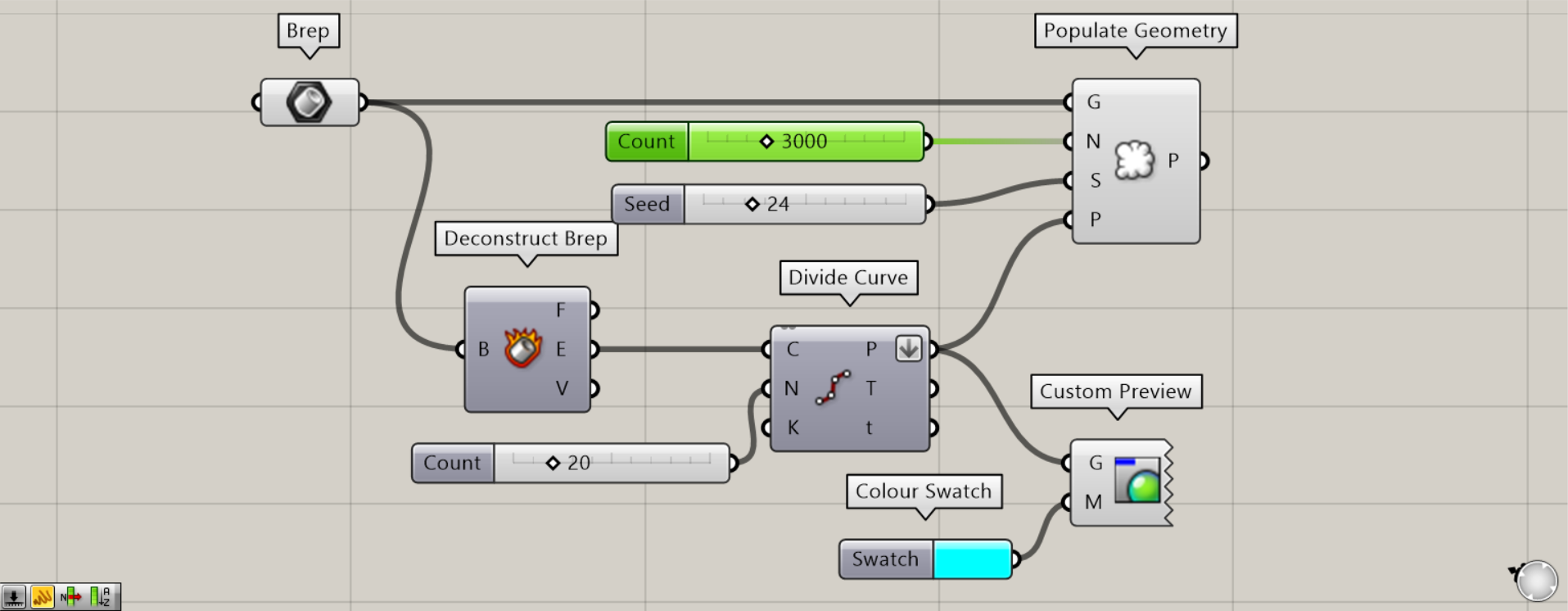
Let’s increase the number of points in the Populate Geometry(N) from 1000 to 3000 and increase the density of points.
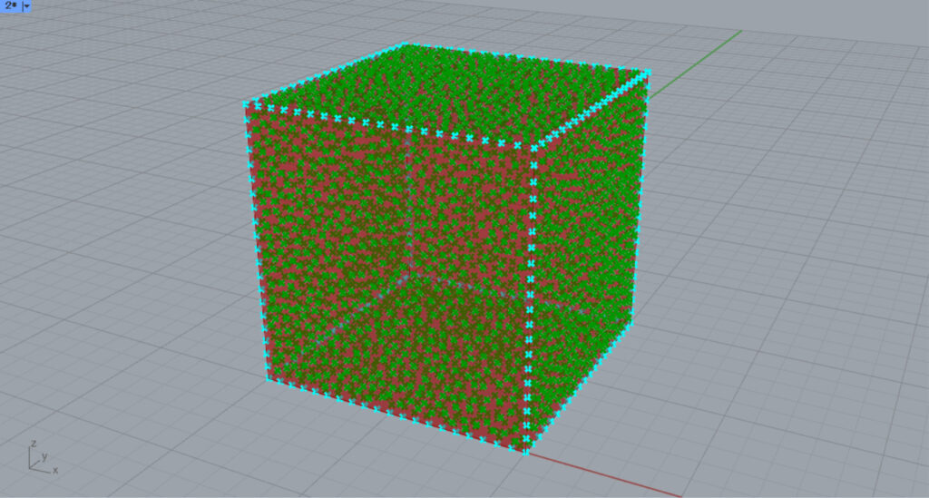
The higher the density of points, the closer the points are to the border, even when the P is specified.
List of Grasshopper articles using Populate Geometry component↓

Comment