
![[Grasshopper] How to use Angle Dimension (Arc) to Create and Edit Angle Dimensions](https://iarchway.com/wp-content/uploads/2026/01/Angle-Dimention-Arc.png)
This article explains how to use Angle Dimension (Arc) to create and edit angle dimensions.
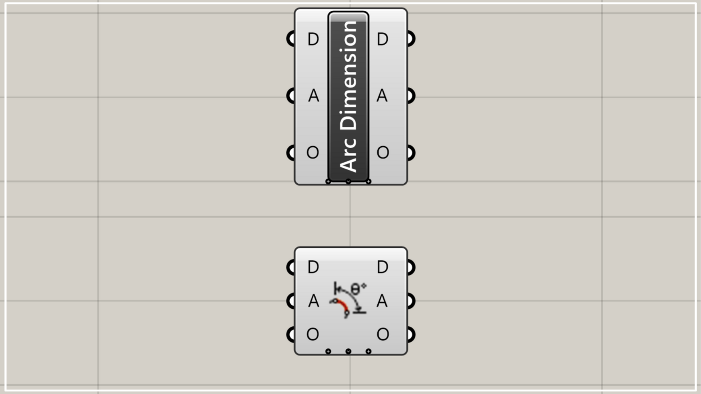
On the Grasshopper, it is represented by either of the two above.
Create and edit angular dimensions
Using Angle Dimension (Arc), you can create and edit angle dimensions.
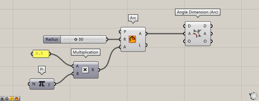
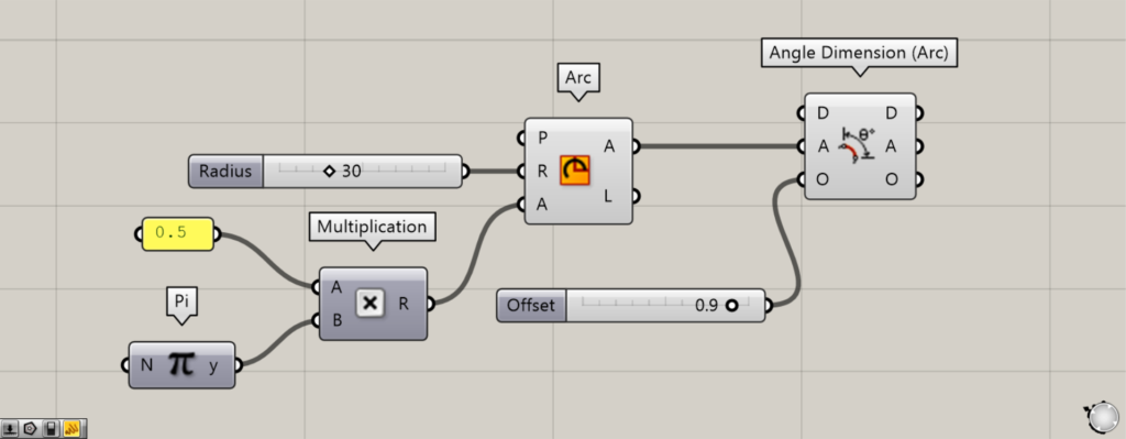
Components Used: ①Pi ②Multiplication ③Arc ④Angle Dimension (Arc)
As a first example, let’s create an angular dimension from an arc.
First, prepare the number 0.5 and Pi.
Next, connect 0.5 and Pi to the Multiplication(A and B), respectively.
Then it is multiplied, creating 0.5π (π/2).
Next, connect the Multiplication to the Arc(A).
Additionally, enter the radius value into the Arc(R).
This time, we entered 30.
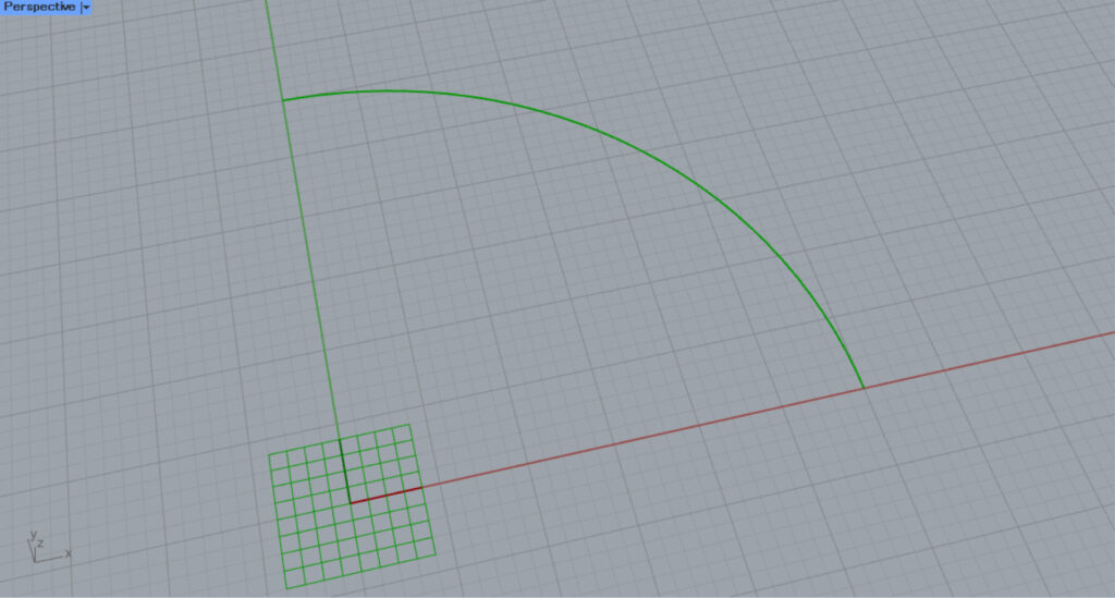
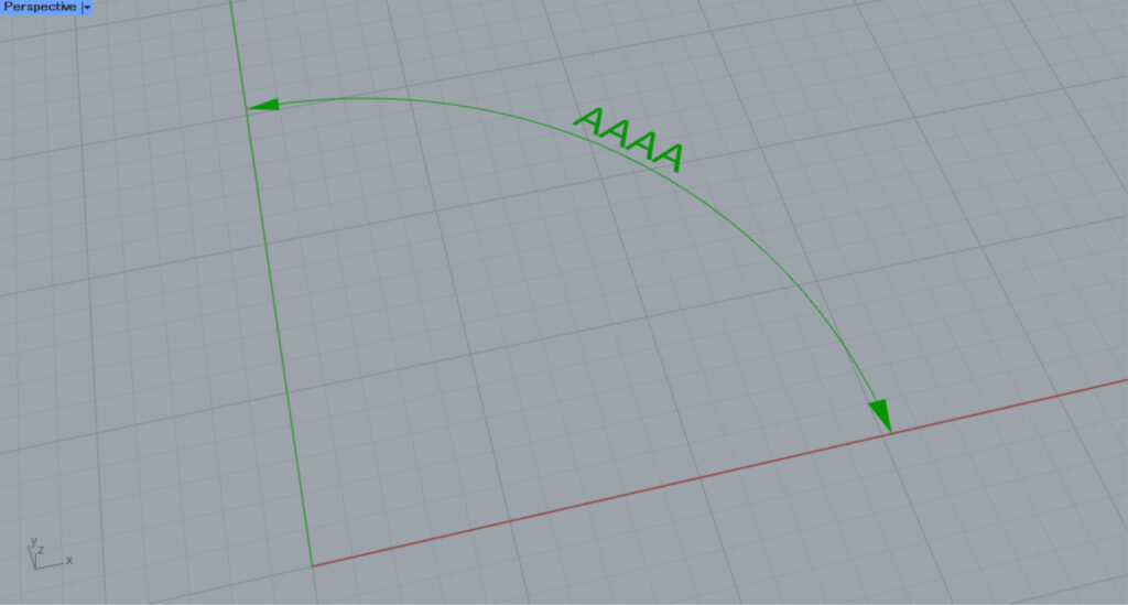
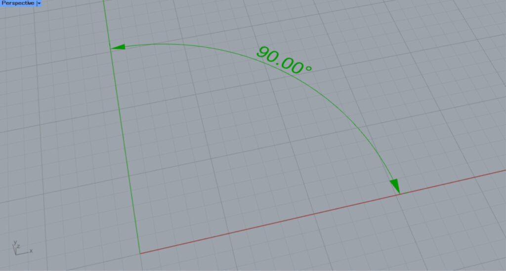
Then, an arc like the one in the image above was created.
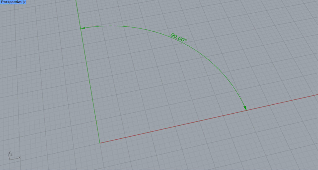
Next, connect the right side of Arc(A) to the A terminal on Angle Dimension (Arc).
Then, an angular dimension was created from the arc.
In this way, using Angle Dimension (Arc) allows you to create angular dimensions from circular arcs.
By entering a numerical value into the O terminal, you can offset the angular dimension.
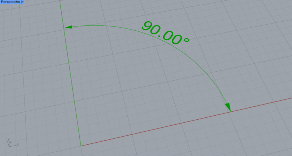
For example, we entered 0.9.
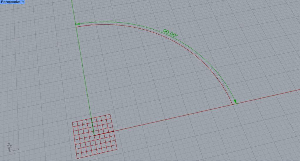
Then, as shown in the image above, the angular dimension was offset by the amount of the entered value.
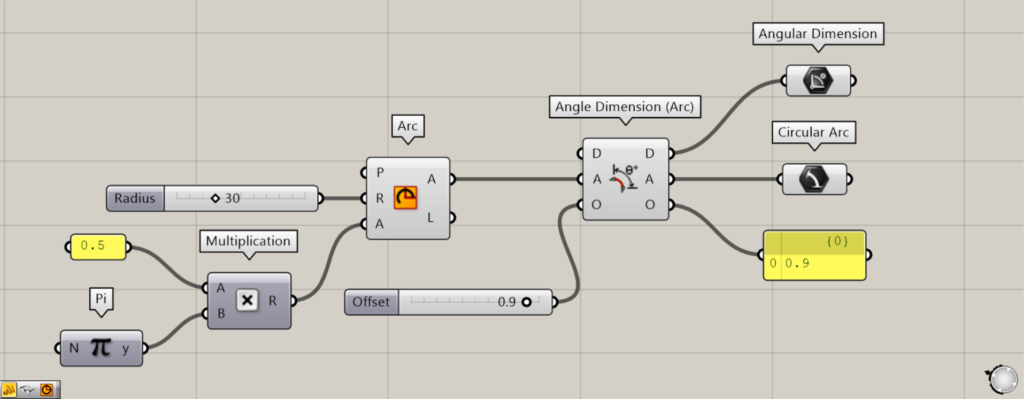
Additional Components: ① Angular Dimension ② Circular Arc
Let’s take a look at the data output from Angle Dimension (Arc).
The D terminal outputs the created angular dimensions.
From Terminal A, the arc data used to create the angular dimensions is output.
The O terminal outputs a numerical value representing the offset distance.
Next, let’s try editing an existing angle dimension.
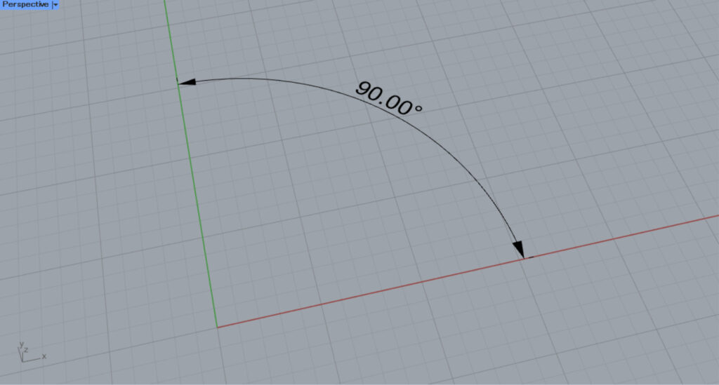
This time, we’ll edit the angular dimensions on Rhino.
Components Used: ① Angular Dimension ② Angle Dimension (Arc)
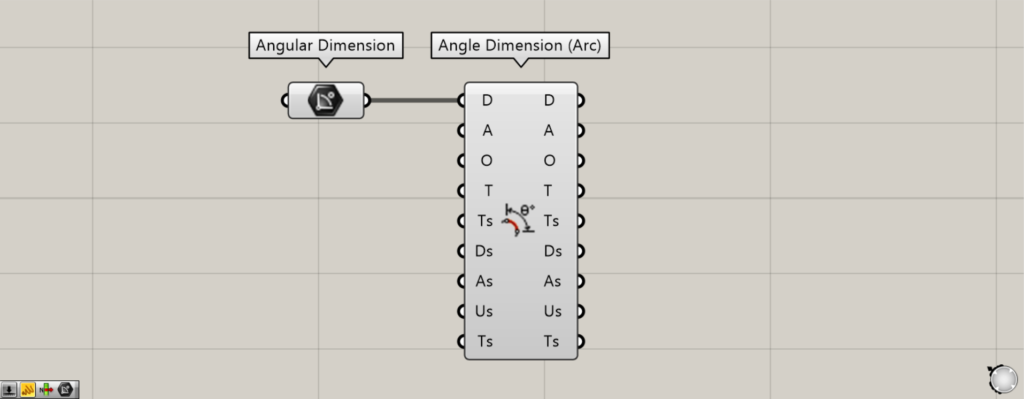
Set the angular dimensions from Rhino in the Angular Dimension.
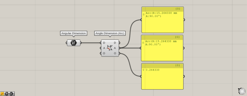
Then, connect the Angular Dimension to the D terminal of the Angle Dimension (Arc).
Then, the angle dimension on rhino will be reflected in the Angle Dimension (Arc).
Therefore, when you look at the output data, you can see the angular dimensions, the arc, and the offset distance information.
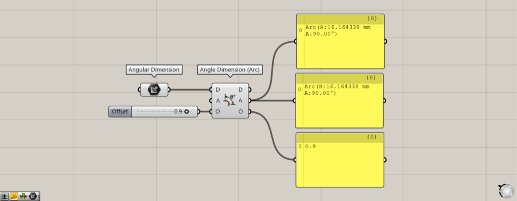
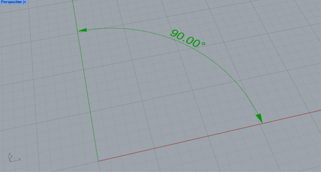
For example, let’s edit the offset value for the O terminal.
This time, we entered 0.9 into the O terminal.
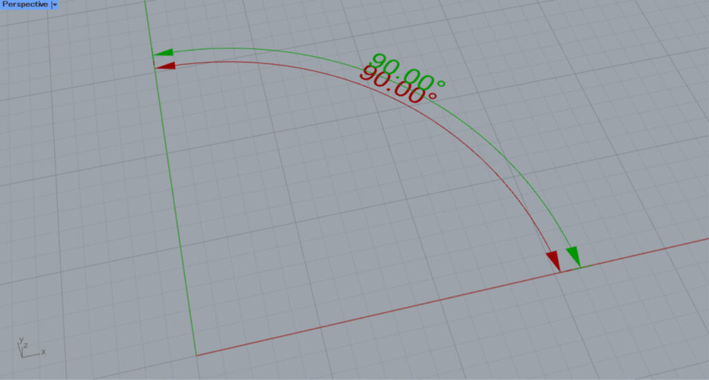
Then, we were able to edit the offset distance from the original angular dimension.
In this way, you can also edit existing angle dimensions.
Detailed Angle Dimension Settings
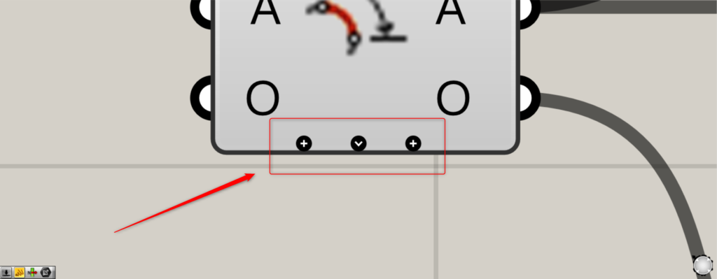
When you zoom toward the Angle Dimension (Arc), a plus sign and arrow appear.
Pressing the plus sign will display one new terminal at a time.
When the arrow mark is displayed, all terminals that can be newly edited will be shown.
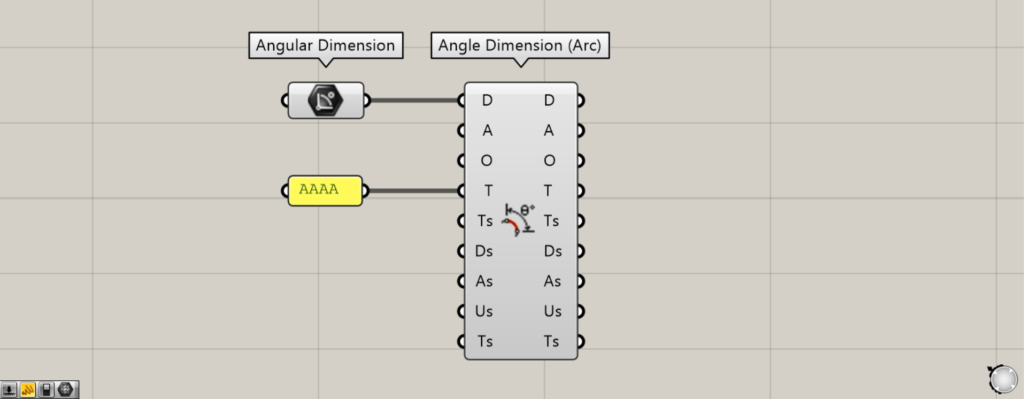
By entering character data into the T terminal, you can edit the displayed text.
As you can see, the displayed characters have changed.
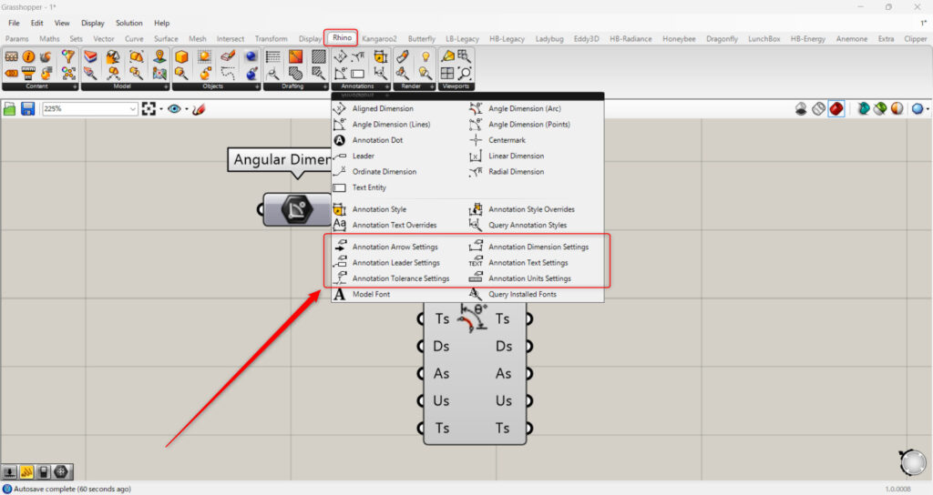
The Ts, Ds, As, Us, and Ts terminals can be configured in detail using the lower components in the Rhino tab.
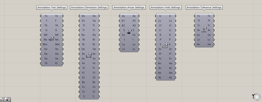
For the Ts terminal, use the Annotation Text Settings.
The Ts terminal allows you to configure text settings.
For the Ds terminal, use Annotation Dimension Settings.
The Ds terminal allows you to set dimensions.
For the As terminal, use the Annotation Arrow Settings.
On the As terminal, you can configure the arrow settings.
For the Us terminal, use Annotation Units Settings.
The Us terminal allows you to set the unit.
For the Ts terminal, use the Annotation Tolerance Settings.
The Ts terminal allows you to set the tolerance.
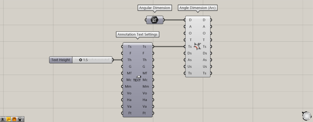
Additional Component: ① Annotation Text Settings
This time, let’s look at an example where the text size was changed in the Annotation Text Settings.
The original angular dimension size.
we entered 1.5 into the Th terminal of the Annotation Text Settings.
Then, the font size increased.
In this way, the Ts, Ds, As, Us, and Ts terminals allow for detailed configuration.
List of Grasshopper articles using Angle Dimension (Arc) component↓

Comment