
![[Grasshopper] How to use Ordinate Dimension to create coordinate dimensions](https://iarchway.com/wp-content/uploads/2026/01/Ordinate-Dimension.png)
This article explains how to use Ordinate Dimension to create coordinate dimensions.
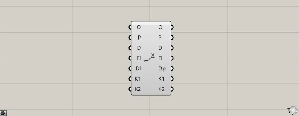
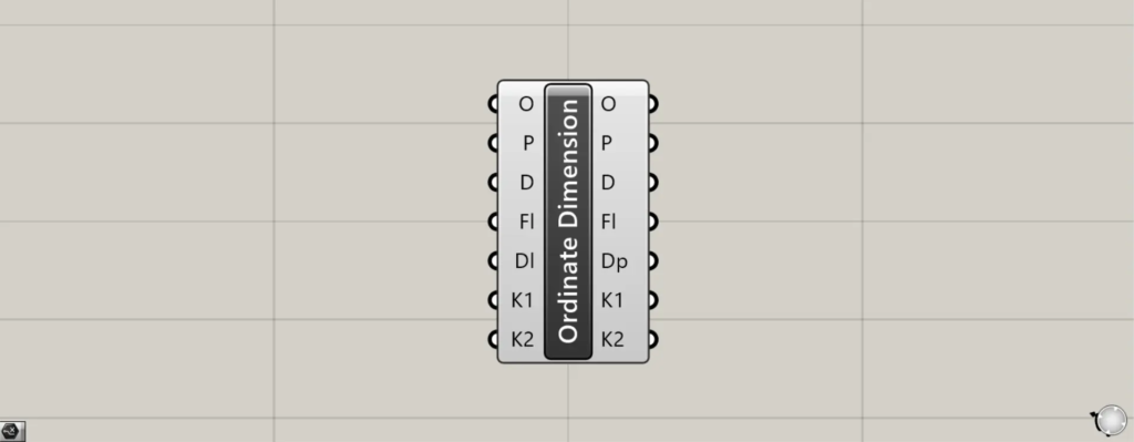
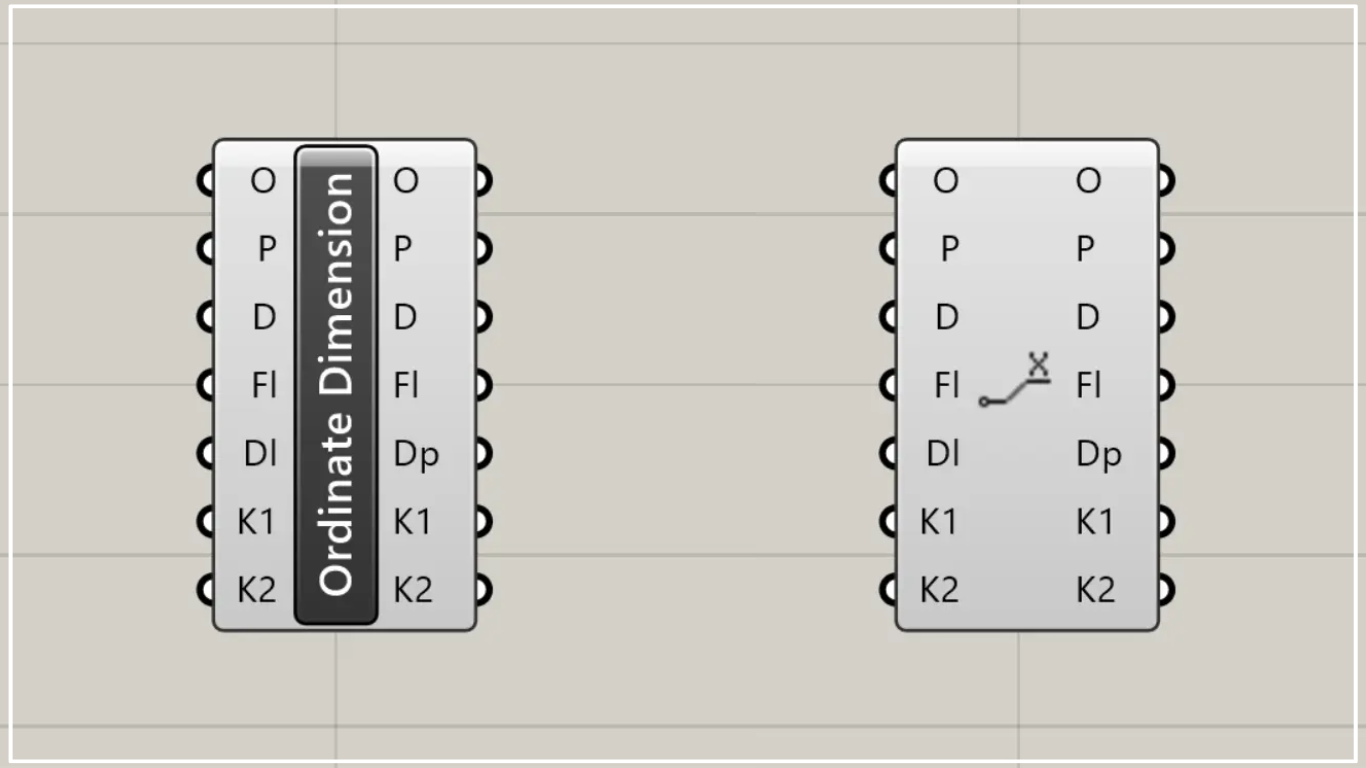
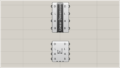
On the Grasshopper, it is represented by either of the two above.
Create coordinate dimensions
Using the Ordinate Dimension allows you to create coordinate dimensions.
In the Ordinate Dimension, two points are used.
In Ordinate Dimension, you can create a coordinate dimension for the position of a second specified point, using a first specified point as the reference.
For clarity, think of the first point you specify as the origin.
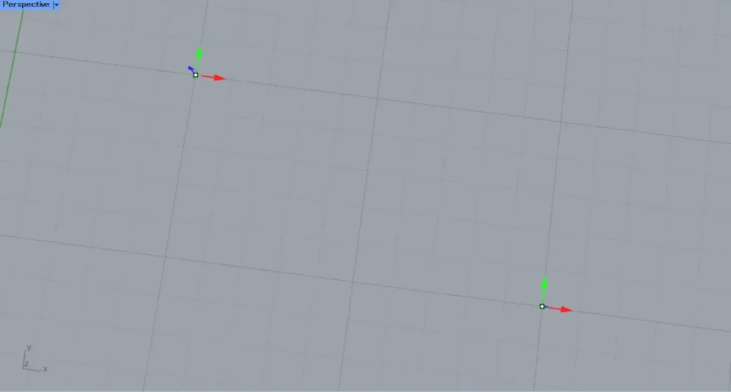
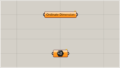
This time, we will use the two points in the image above.
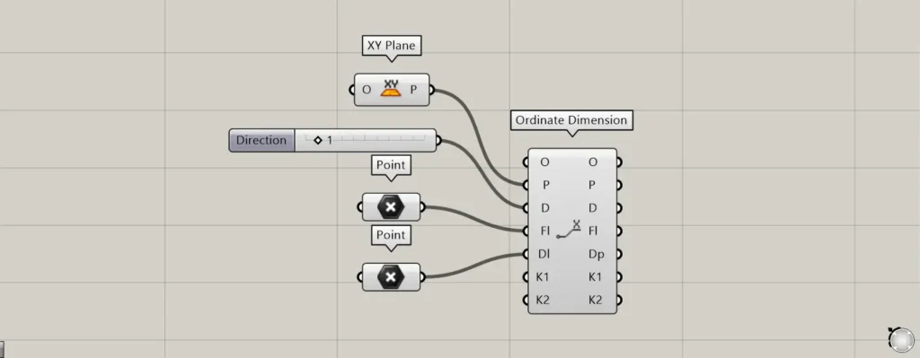
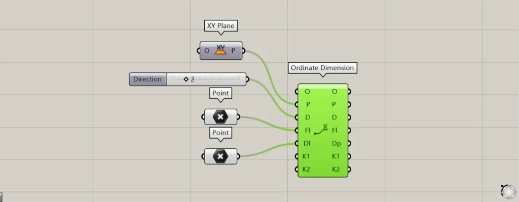
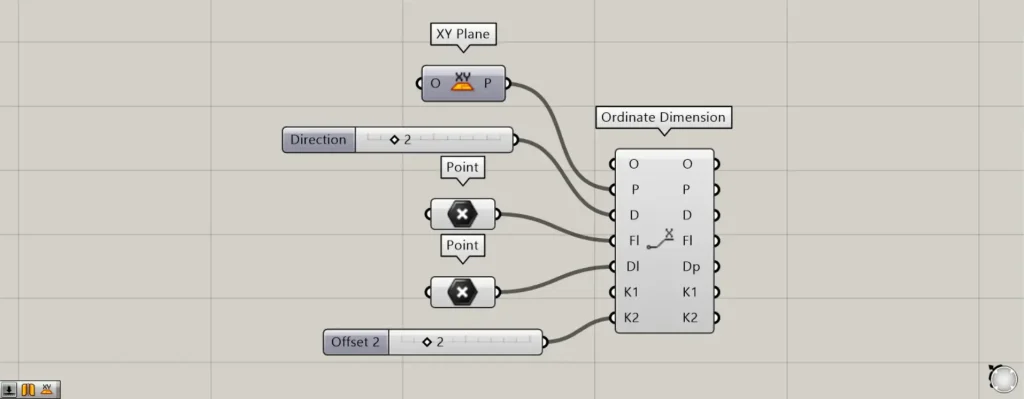
Components used: ① XY Plane ② Point ③ Ordinate Dimension
Connect the information for the plane where coordinate dimensions are created to the Ordinate Dimension(P).
If no input is provided, the plane formed by the X and Y axes will be specified by default.
This time, as an example, we are connecting the XY Plane.
By entering either 1 or 2 into the Ordinate Dimension(D), you can specify whether to create vertical or horizontal coordinate dimensions.
For case 1, you can obtain the vertical coordinate dimension; for case 2, you can obtain the horizontal coordinate dimension.
Initially, the value 1 is entered.
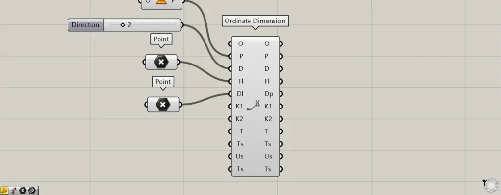
Then, connect the starting point data to the Ordinate Dimension(FL).
Furthermore, connect the endpoint point data to Ordinate Dimension(DL).
This time, the two points set in Point are connected to the Ordinate Dimension(FL) and Ordinate Dimension(DL), respectively.
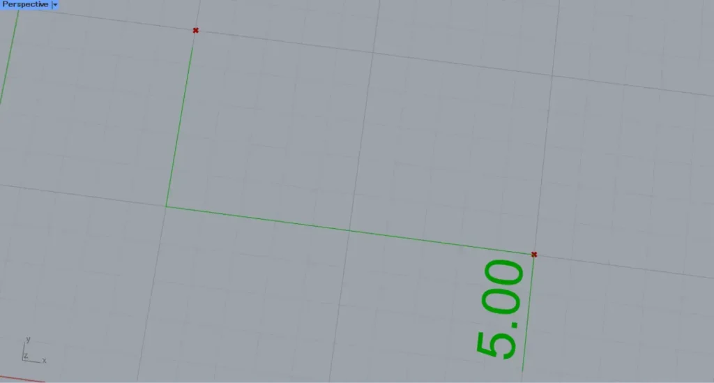
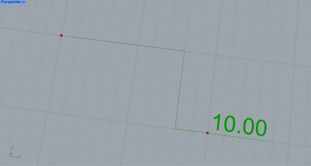
Then, the coordinate dimensions will be created.
This time, since the value 1 is entered into the Ordinate Dimension(D), the vertical coordinate dimension has been created.
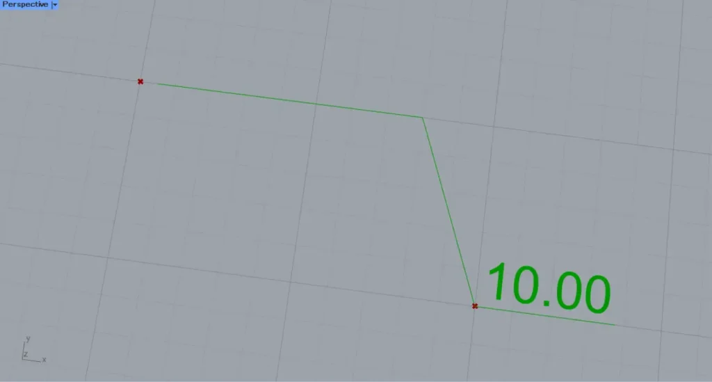
I changed the value of the Ordinate Dimension(D) to 2.
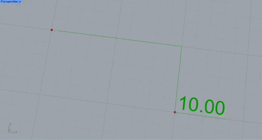
Then, the horizontal coordinate dimensions were created as shown.
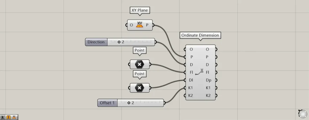
By entering values into the Ordinate Dimension(K1 and K2), you can offset dimension lines.
For example, let’s first input 2 into Ordinate Dimension(K1).
Then, the vertical line was offset, changing the shape of the dimension line.
In this case, the vertical line has shifted by the specified amount of 2 units to the left from the endpoint position.
Next, let’s input 2 into the Dimension(K2).
Then, only one end of the original vertical line is offset.
In this case, only the end portion is moving to the left by the specified amount of 2.
Extract the components of existing coordinate dimensions
You can also extract the components of existing coordinate dimensions.
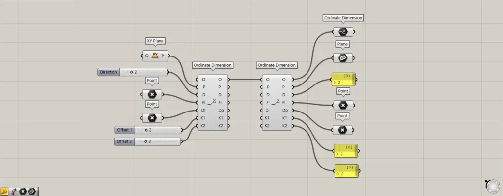
Additional Components: ①Ordinate Dimension ②Plane
Connect the existing coordinate dimension data to the Ordinate Dimension(O).
Then, you can retrieve the data for each element that makes up the coordinate dimensions from the terminal on the right.
Configure detailed coordinate dimensions
You can also configure detailed coordinate dimensions.
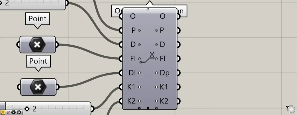
When you zoom toward the Ordinate Dimension component, a plus and arrow icon appears at the bottom.
Pressing these icons will display new terminals.
When all terminals are displayed, the T, Ts, Us, and Ts terminals will be displayed additionally.
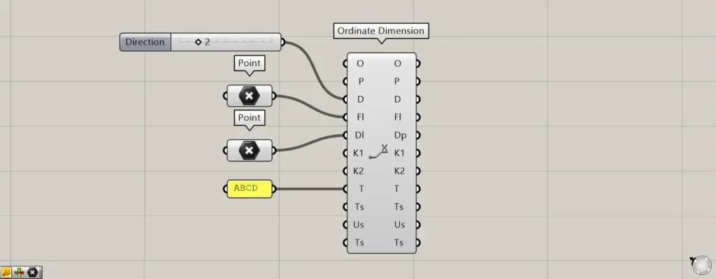
You can set the values and texts displayed on the T terminal.
This time, we entered ABCD.
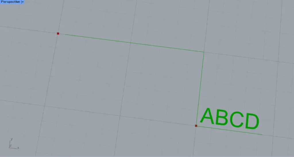
Then, the displayed numbers and texts changed.
In this case, it is displayed as the specified ABCD.
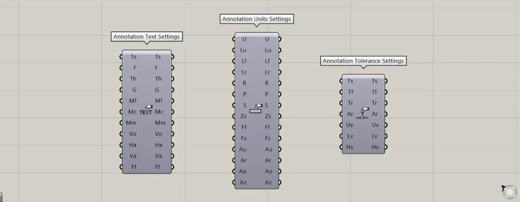
Components used for detailed settings: ① Annotation Text Settings ② Annotation Units Settings ③ Annotation Tolerance Settings
For the Ts, Us, and Ts terminals, use the components shown in the image above for each.
For the Ts terminal, use the Annotation Text Settings.
The Ts terminal allows you to configure text settings.
For the Us terminal, use Annotation Units Settings.
The Us terminal allows you to set the unit.
For the second Ts terminal, use the Annotation Tolerance Settings.
The second Ts terminal allows you to set the tolerance.
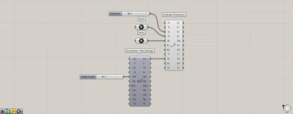
This time, as an example, we’ll configure the detailed settings for the text displayed on the first Ts terminal.
By entering the number 2 in the MF terminal of the Annotation Tolerance Settings, you can create a capsule-like border around the displayed text.
Next, connect the Ts terminal on the right side of the Annotation Tolerance Settings to the Ts terminal on the left side of the Ordinate Dimension.
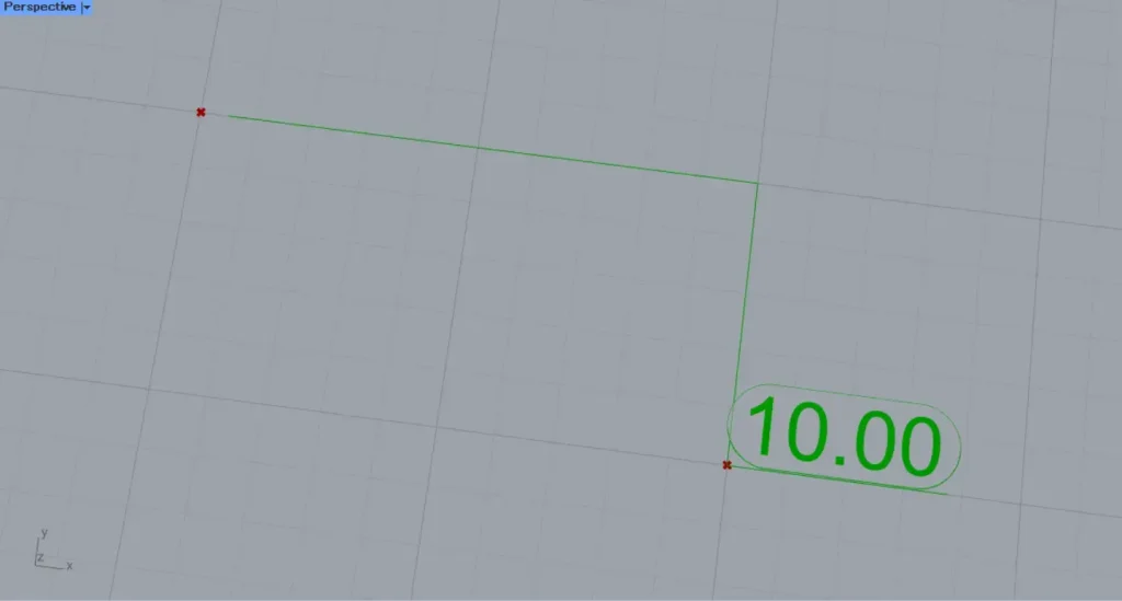
Then, we were able to create a capsule-like enclosure around the text like this.
In this way, you can configure various detailed settings using the additional terminals.
List of Grasshopper articles using Ordinate Dimension component↓

Comment