
![[Grasshopper] How to use Radial Dimension to create radius dimensions](https://iarchway.com/wp-content/uploads/2026/01/Radial-Dimension-1.png)
This article explains how to use Radial Dimension to create radius dimensions.
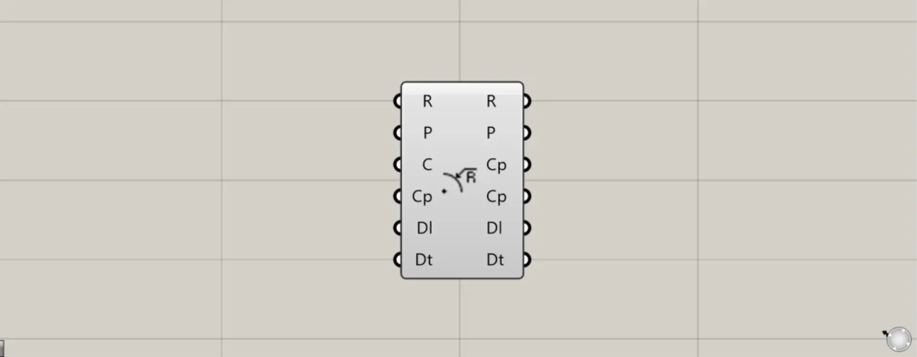
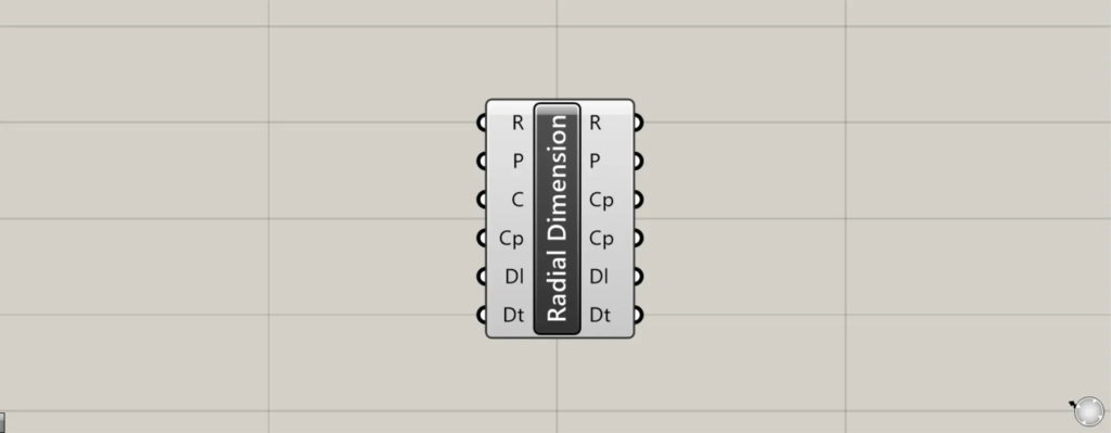
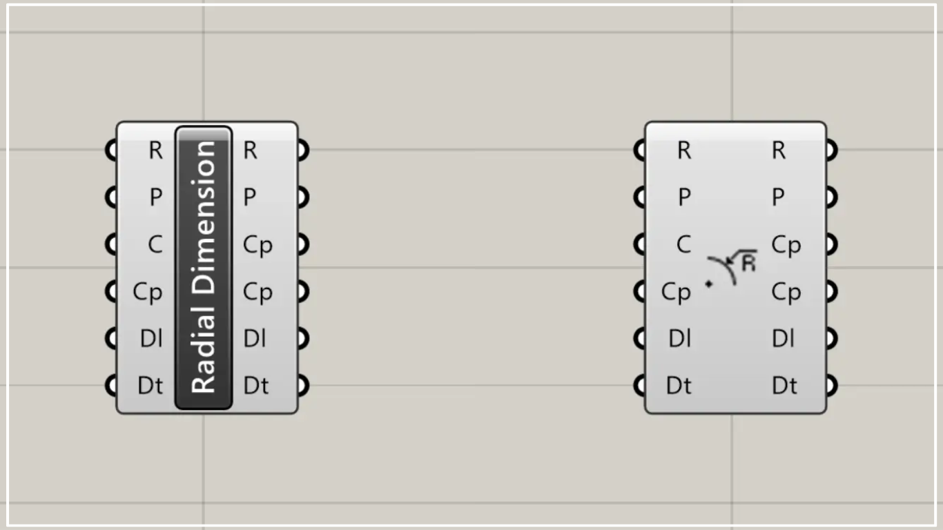
On the Grasshopper, it is represented by either of the two above.
Create radius dimensions
Using the Radial Dimension allows you to create radial dimensions.
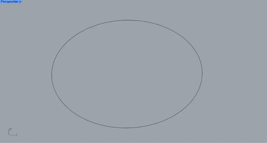
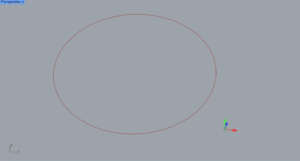
In the first example, we’ll use the circle on Rhino to explain.
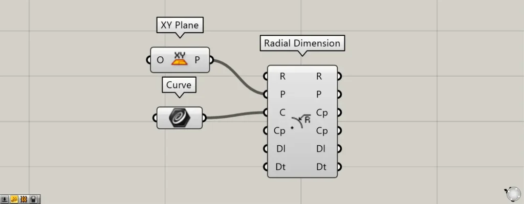
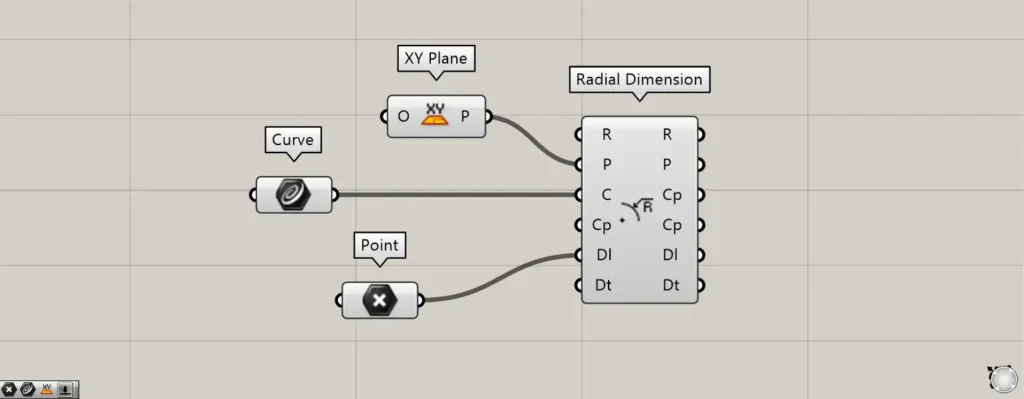
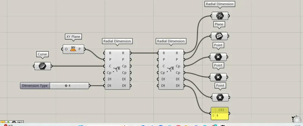
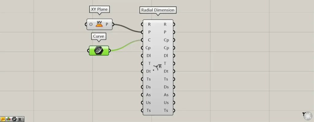
Components used: ① XY Plane ② Curve ③ Radial Dimension
Connect the Radial Dimension(P) to the plane information where the radial dimension will be created.
If nothing is entered, the plane created from the X and Y axes is set as the default.
This time, we set up a plane created from the X and Y axes using the XY Plane.
Input circular or curved line data into the Radial Dimension(C).
This time, we are connecting the circular data set in Curve.
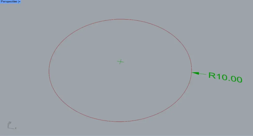
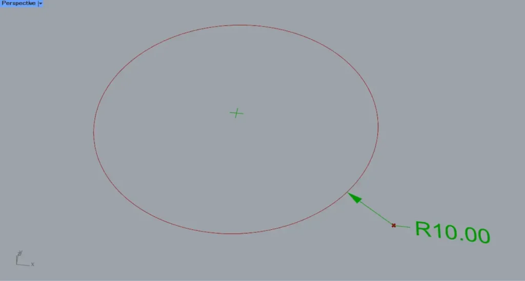
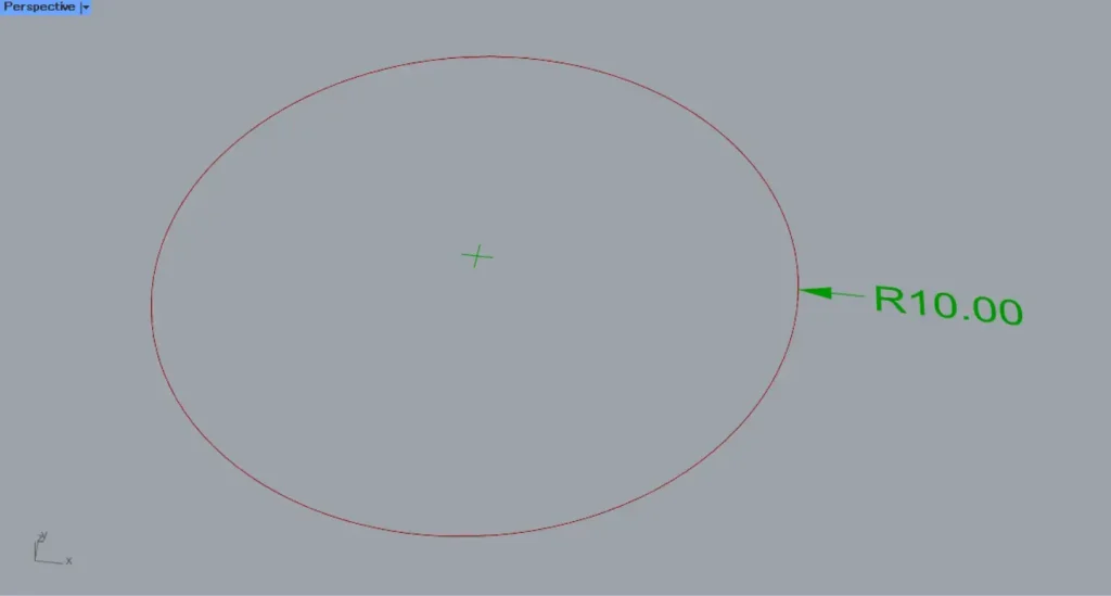
Then, the radius dimension was created as shown.
This time, a circle with a radius of 10 was used, so it is displayed as R10.00.
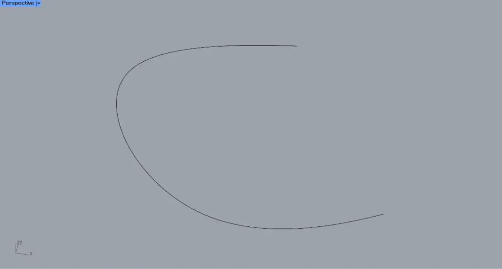
As the next example, we will explain how to use the Cp terminal using a curve like the one shown in the image above on Rhino.

Additional Component: ①Evaluate Curve
By specifying a point on a circle or curve at the Cp terminal, a radius dimension is created using the center point at that location.
Set the curve from the Rhino on Curve.
Then connect the Curve to the Evaluate Curve(C).
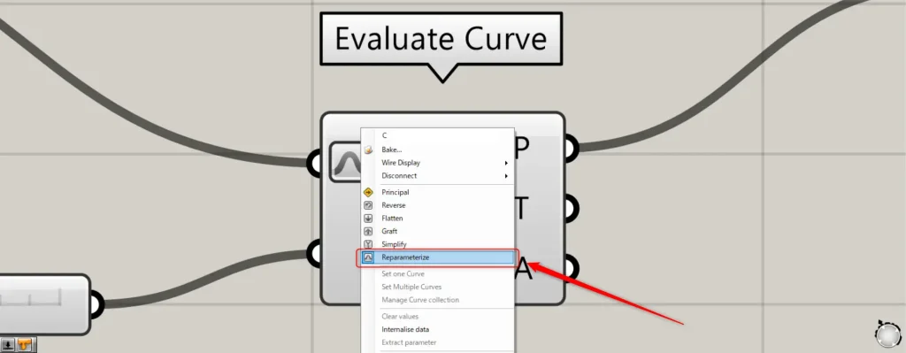
At this point, right-click the C terminal of the Evaluate Curve and select “Reparameterize”.
This allows you to specify points on the curve using values between 0 and 1.0.
Then, enter a value between 0 and 1.0 into the the Evaluate Curve(t).
Initially, 0.2 is entered.
Next, connect the Evaluate Curve(P) to the Radial Dimension(Cp).
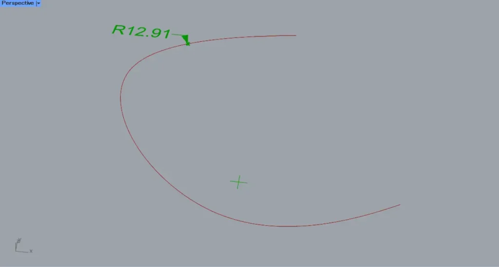
When the t-terminal value is set to 0.2, a radius dimension will be created at the position shown in the image above.
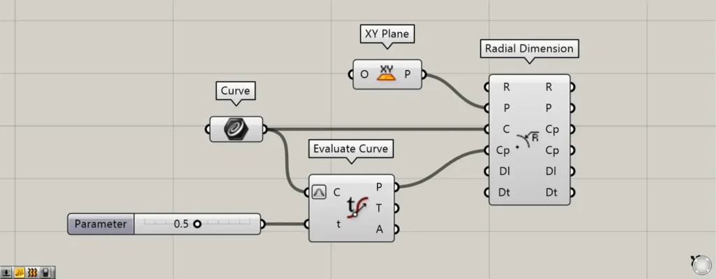
Let’s change the value of terminal t to 0.5.
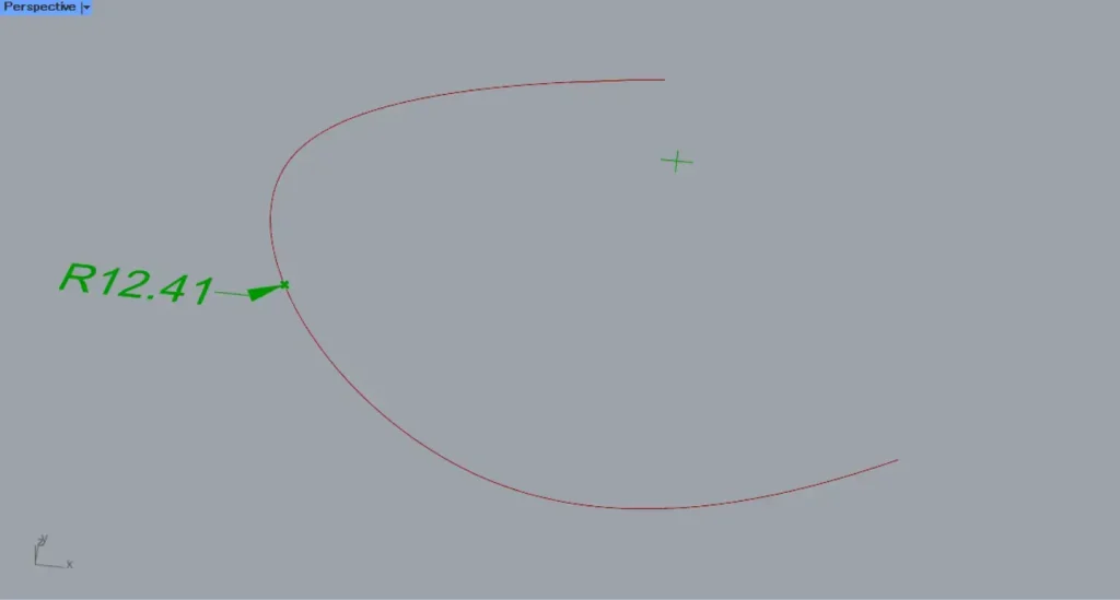
When the t-terminal value was set to 0.5, the radius dimension at the center position of the curve was created.
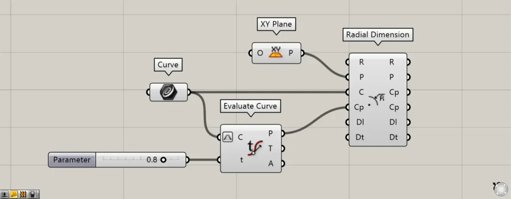
We’ll change the value of terminal t to 0.8.
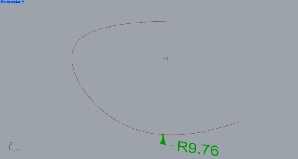
When the t-terminal value is set to 0.8, a radius dimension will be created at the position shown in the image above.
In this way, by specifying a point on a circle or curve at the Cp terminal, you create a radius dimension using the center point at that location.
Next, using the point shown in the image above, let’s examine the Dl terminal.
Additional Component: ①Point
Connect the information of points created at any location to the Radial Dimension(Dl).
This time, the point set in Point is connected to the Radial Dimension(Dl).
Then, an arrow will appear from the points created in this manner.
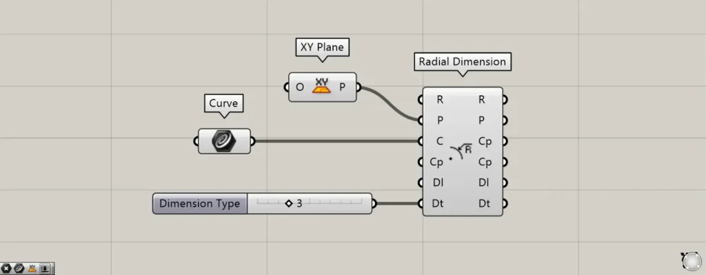
For the Dt terminal, you can specify the display format for the radius dimension by connecting the values 3 or 4.
First, let’s try entering the number 3.
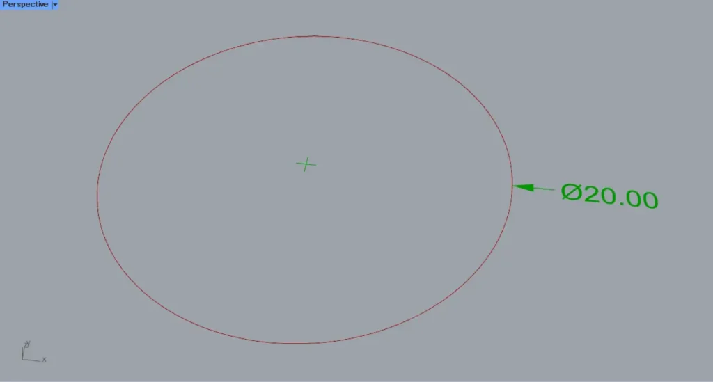
If you enter 3, Φ (Phi) will appear at the beginning of the number.

Let’s change the value of the Dt terminal to 4.
If you enter 4, R will appear at the beginning of the number.
Extract existing radius dimension components
You can also extract existing radius dimension components.
Additional Components: ① Radial Dimension ② Plane
Connect the existing radial dimension data to the R terminal on the left side of the Radial Dimension.
Then, you can retrieve the data for each element that constitutes the radius dimension from the terminal on the right.
Configure detailed radius dimensions
You can also configure detailed radius dimensions.
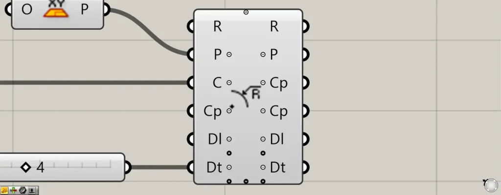
When you zoom toward the Radial Dimension component, a plus and arrow icon appears at the bottom.
Pressing these icons will display new terminals that can be used for detailed radius dimension settings.
When all terminals are displayed, the T, Ts, Ds, As, Us, and Ts terminals will be displayed additionally.
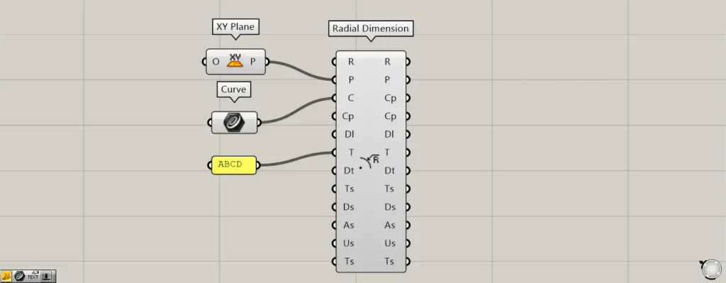
You can configure the values and texts displayed on the T terminal.
This time, as an example, we entered ABCD.
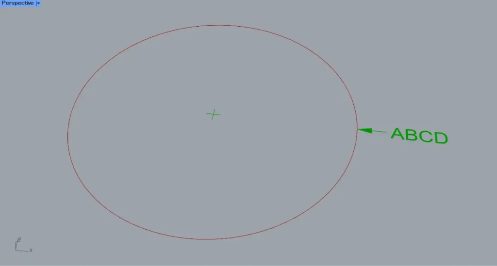
Then, as shown in the image above, the texts and numerical values used for the radius dimension changed.
In this case, it displays the entered ABCD.
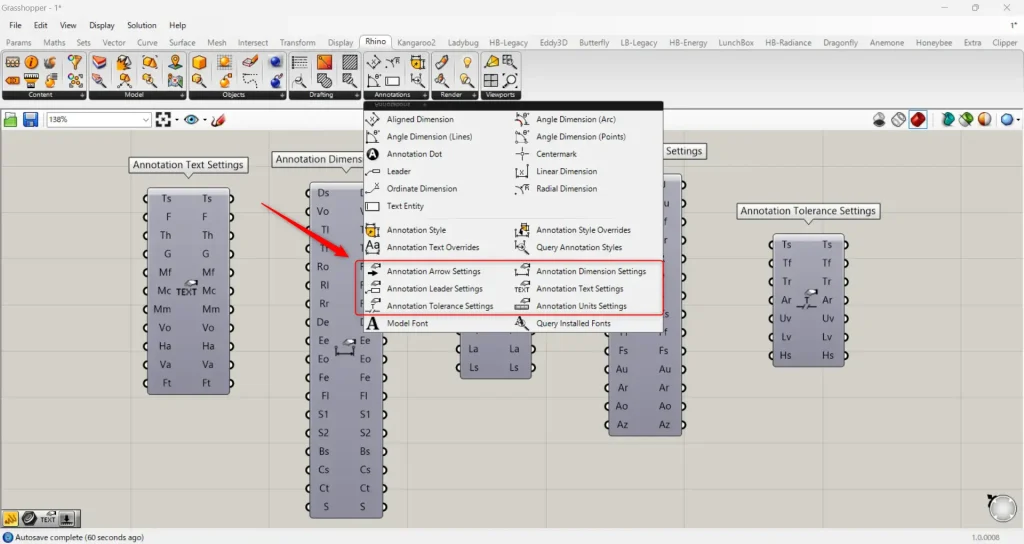
The Ts, Ds, As, Us, and Ts terminals allow detailed radius dimension settings using the lower components in the Rhino tab.
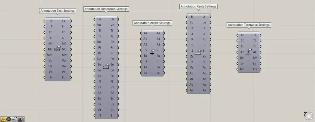
Components used for detailed settings: ① Annotation Text Settings ② Annotation Dimension Settings ③ Annotation Arrow Settings ④ Annotation Units Settings ⑤ Annotation Tolerance Settings
For the Ts terminal, use the Annotation Text Settings.
The Ts terminal allows you to configure text settings.
For the Ds terminal, use Annotation Dimension Settings.
The Ds terminal allows you to set dimensions.
For the As terminal, use Annotation Arrow Settings.
On the As terminal, you can configure the arrow settings.
For the Us terminal, use Annotation Units Settings.
The Us terminal allows you to set the unit.
For the Ts terminal, use the Annotation Tolerance Settings.
The Ts terminal allows you to set the tolerance.
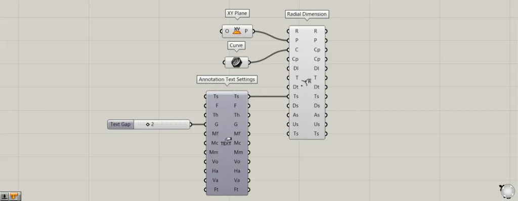
Additional Component: ① Annotation Text Settings
As an example, let’s specify the space distance between arrows and text in the Annotation Text Settings.
Enter the value 2 into the G terminal of the Annotation Text Settings.
Next, connect the right Ts terminal of the Annotation Text Settings to the left Ts terminal of the Radial Dimension.
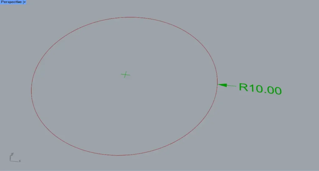
This is how it looked before using Annotation Text Settings.
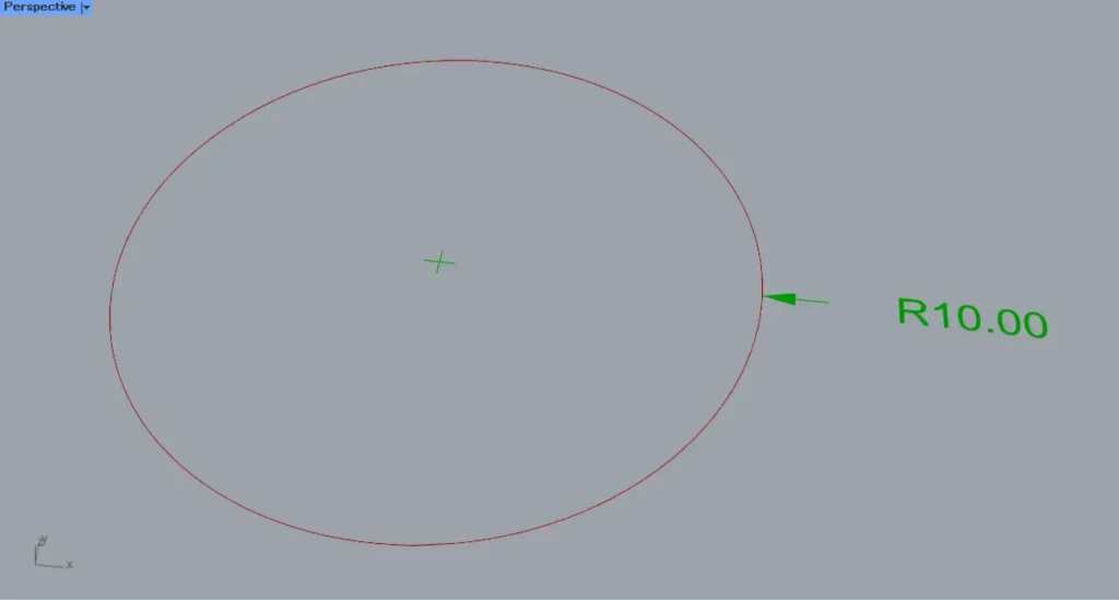
After using Annotation Text Settings, the spacing between the arrow and text changed.
In this way, you can configure various detailed settings.
List of Grasshopper articles using Radial Dimension component↓

Comment