
When using Grasshopper, you may find yourself wanting to rotate objects.
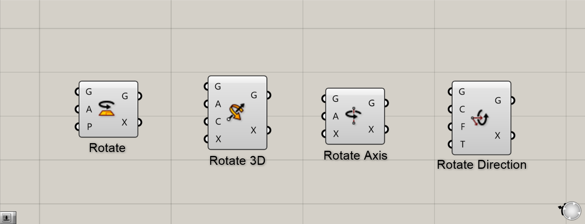
So this time, we’ll introduce four practical rotating components you can actually use.
The Grasshopper and Rhino data for this session can be downloaded from the link below.
Download Grasshopper and Rhino data here
For information regarding the use of downloadable data, please refer to the Terms of Use.
First thing to keep in mind
Before beginning the component explanation, please set the angle unit to Degrees for the rotation meter system.
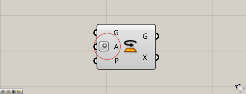
By setting this mark on the A (Angle) terminal, You can determine angles using degrees.
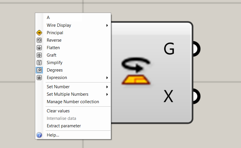
Right-click the A terminal to set the Degrees.
Rotate Component
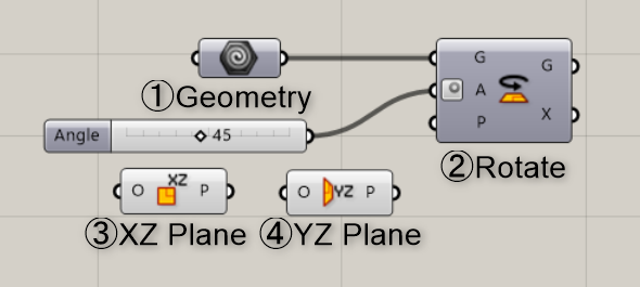
Components used: ① Geometry ② Rotate ③ XZ Plane ④ YZ Plane
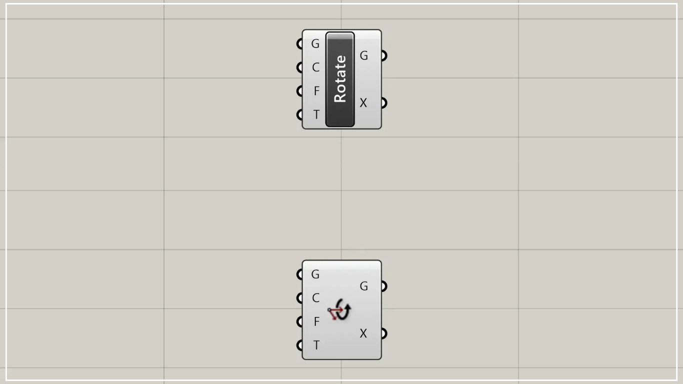
First, we’ll explain the Rotate component.
This component is the simplest and most frequently used.
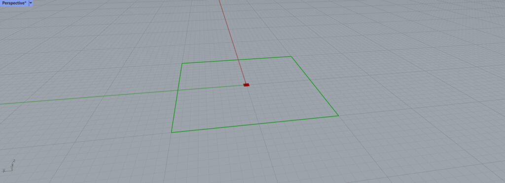
In this case, we set the object to rotate in the Geometry.
This time, we set the square on Rhino.
Here, as an example, we will rotate it by 45 degrees.
Connect the value 45 to Rotate(A).
This allowed it to be rotated 45 degrees.
However, this is simply rotating it on the XY plane.
Some people might want to rotate it on another plane.
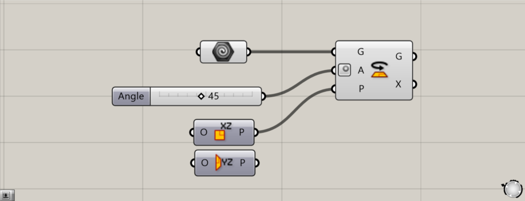
Then connect the XZ Plane to the Rotate(P).
This is a component that can change the plane to the XZ plane.
In short, you can work using a vertical plane as a reference.
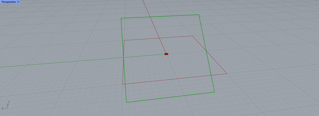
This allowed us to rotate the 45-degree quadrilateral vertically this time.
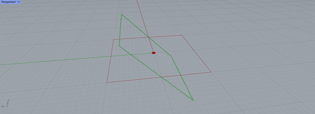
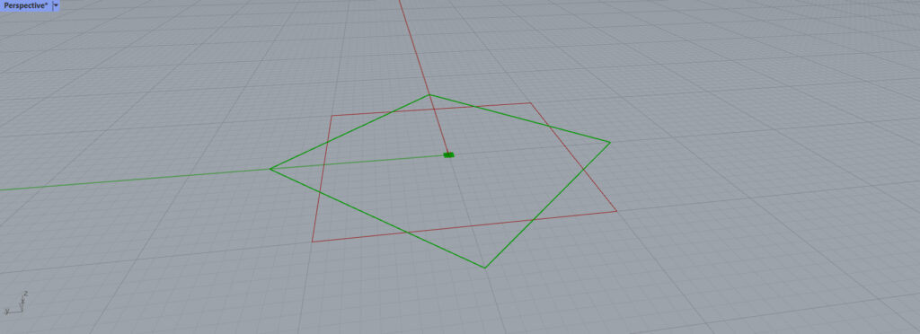
Conversely, setting it to the YZ Plane allows rotation around a different axis.
You can set up the plane in various ways, so try different options to suit your needs.
List of Grasshopper articles using Rotate component↓
Rotate 3D Component
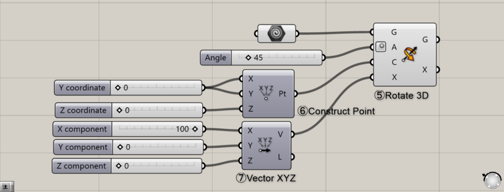
Components used: ⑤ Rotate 3D ⑥ Construct point ⑦ Vector XYZ
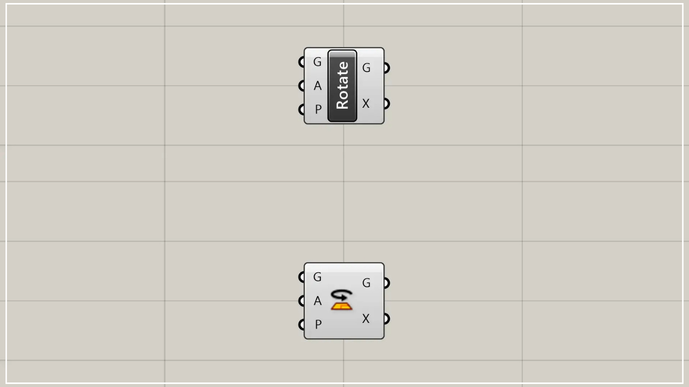
Next is the Rotate 3D component.
This allows you to easily rotate objects in three dimensions.
To rotate an object, you determine the axis of rotation by specifying the center point and the vector.
Use Construct Point to set the reference point.
Here, it is set to the origin at 0,0,0.
Then connect it to the Rotate 3D(C).
Then, use Vector XYZ to determine the vector’s direction and set the rotation axis.
Here, we’ve entered 100 in the X direction. However, the value can be anything—even 1.
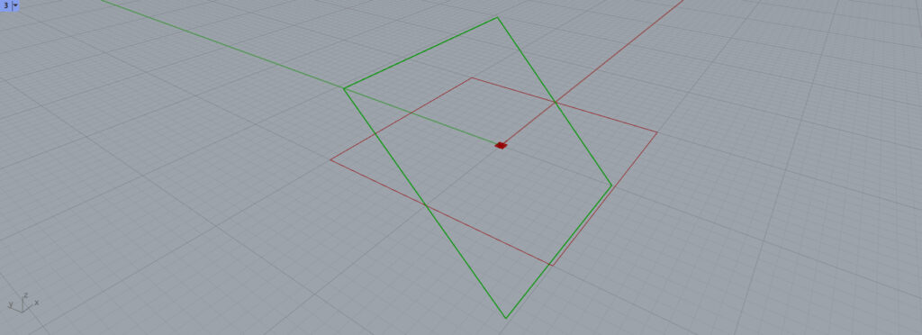
The image is as shown in this diagram. It rotates around the X-axis.
Changing the center point of the Construct Point to 100,100,0 allows you to change the rotation axis like this.
Try adjusting the center point and axis to find the rotation that best suits your model.
List of Grasshopper articles using Rotate 3D component↓
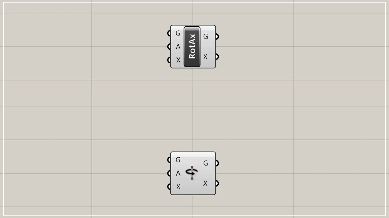
Rotate Axis Component
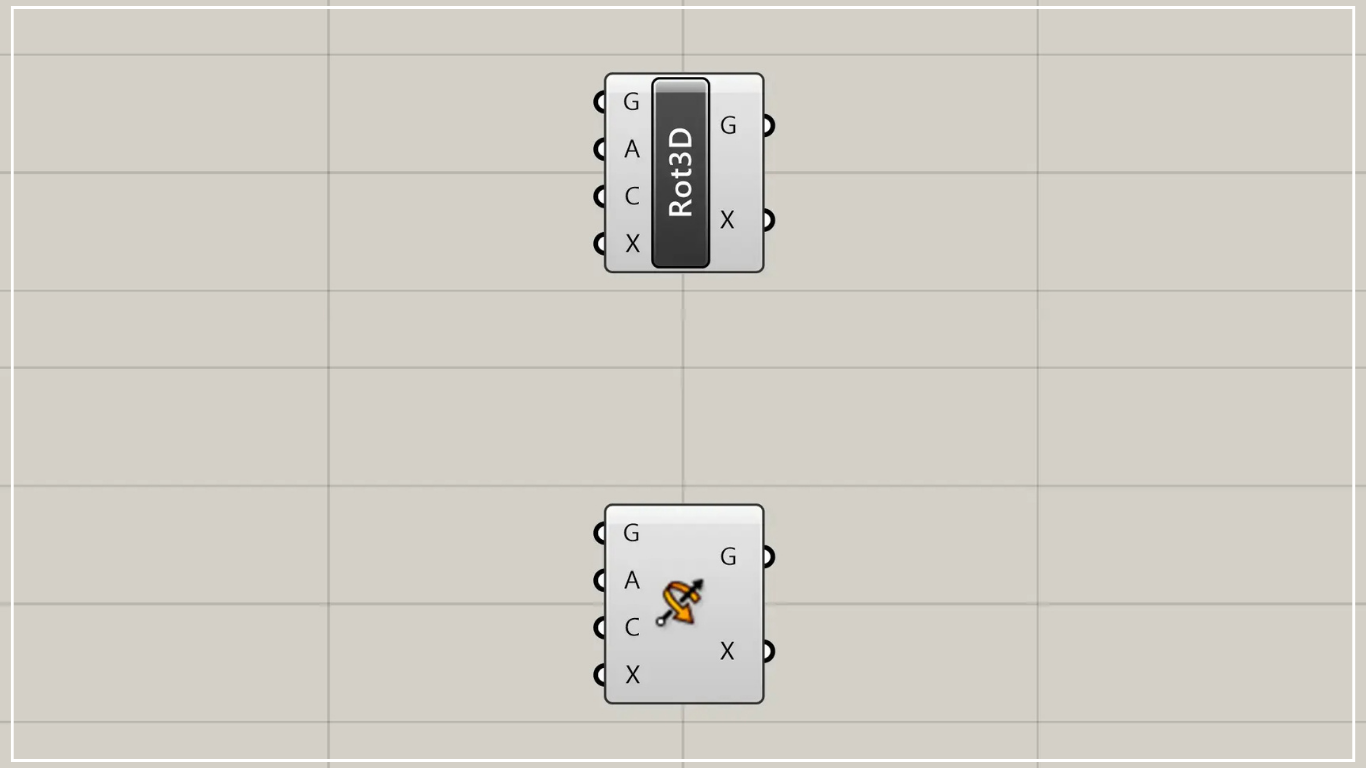
Components used: ⑧ Curve ⑨ Rotate Axis
Next is Rotate Axis.
This component is very similar to the Rotate 3D component we just saw.
The difference lies in whether the axis is generated from the center point and direction, or whether the axis is determined from the outset.
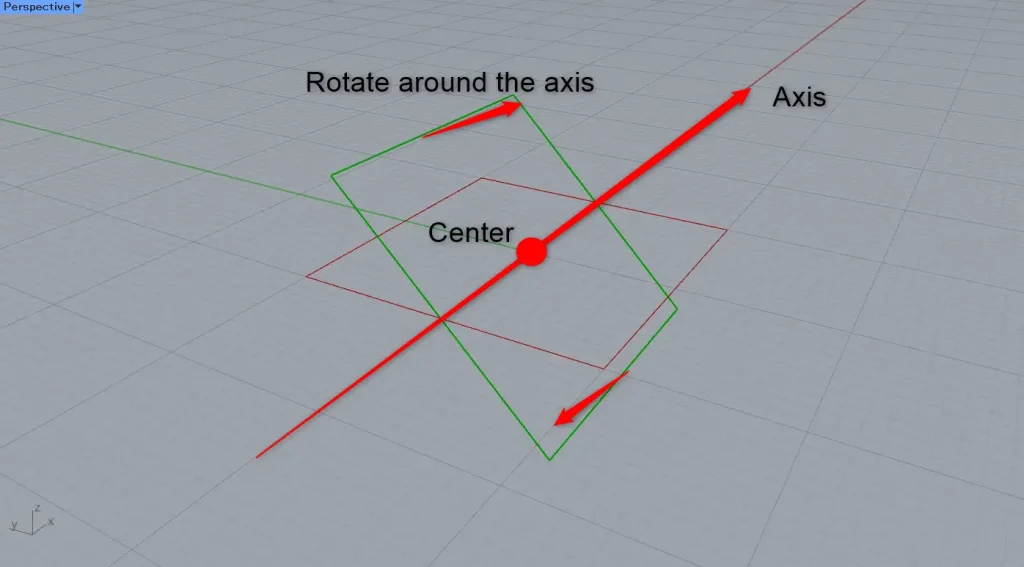
In this case, this method sets the line on Rhino as the axis.
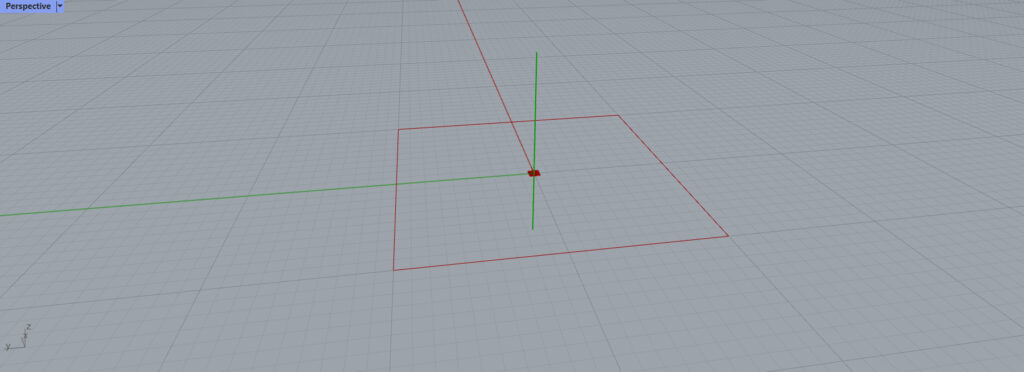
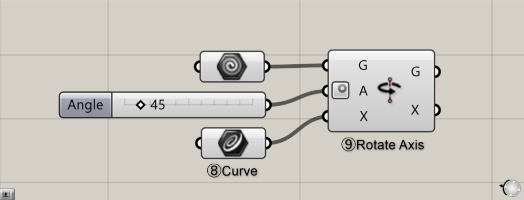
Here, we store the line passing vertically through the origin in Curve.
This line will serve as the center axis around which the quadrilateral rotates.
Then connect this line to the Rotate Axis(X).

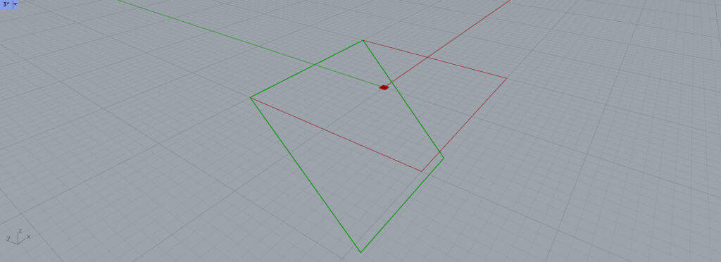
And when rotated 45 degrees, it looks like this.
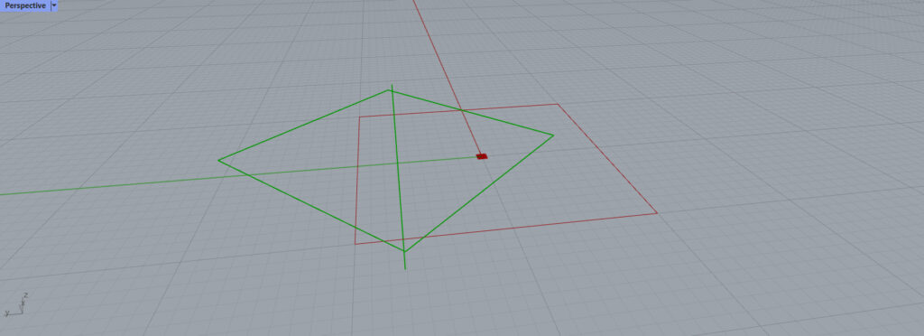
When you shift the axis, the center of rotation for the quadrilateral changes like this.
By setting the orientation and position of the axis in this manner, you can configure various rotation settings.
List of Grasshopper articles using Rotate Axis Component component↓
Rotate Direction Component
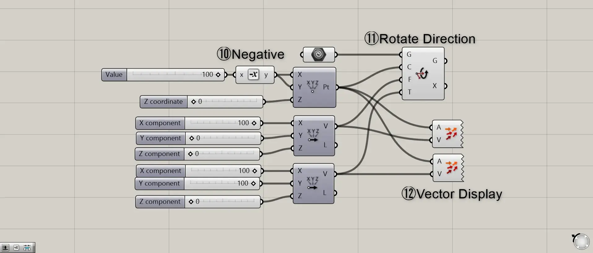
Component Used: ⑩ Negative ⑪ Rotate Direction ⑫ Vector Display
Finally, we’ll introduce Rotate Direction.
This component rotates by defining a center point and two vectors.
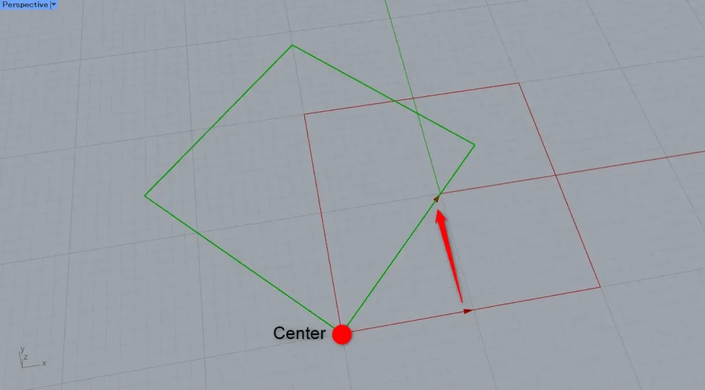
First, as before, use Construct Point to determine the center point.
Connecting 100 to Negative sets the value to -100.
Then, the center point is set to -100, -100, 0.
Connect it to the Rotate Direction(C).
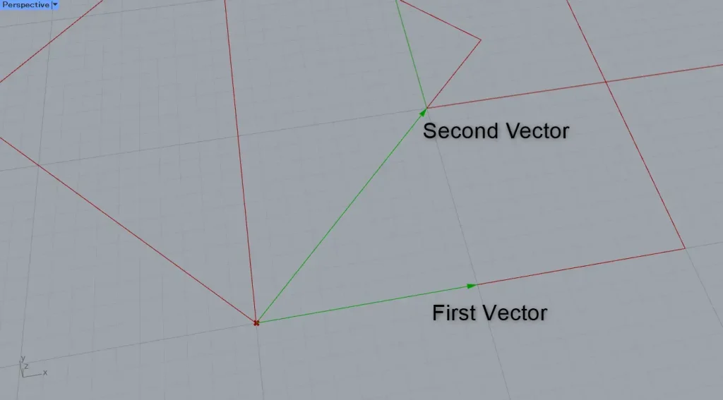
Additionally, two Vector XYZ are used to determine two vectors.
The first one is 100,0,0 and the second one is 100,100,0.
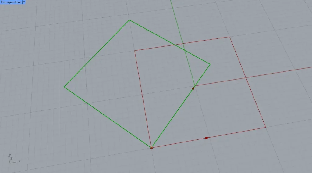
The first vector serves as the reference vector (red) before rotation.
The second step determines the vector (green) at which the rotation ends.
This time, we are visualizing two vectors using Vector Display.
As shown in the image above, the rectangle rotates based on the second vector relative to the first vector.
In this way, using Rotate Direction allows you to rotate the model based on the relationship between two vectors.
List of Grasshopper articles using Rotate Direction Component component↓

Comment