
![[Grasshopper] How to use Centermark to create center mark dimensions](https://iarchway.com/wp-content/uploads/2026/01/Centermark.png)
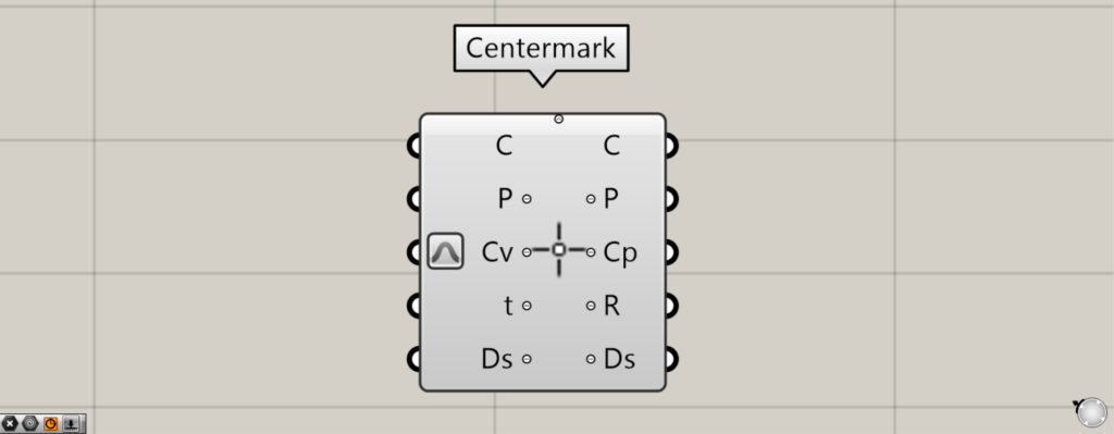
This article explains how to use Centermark to create center mark dimensions.
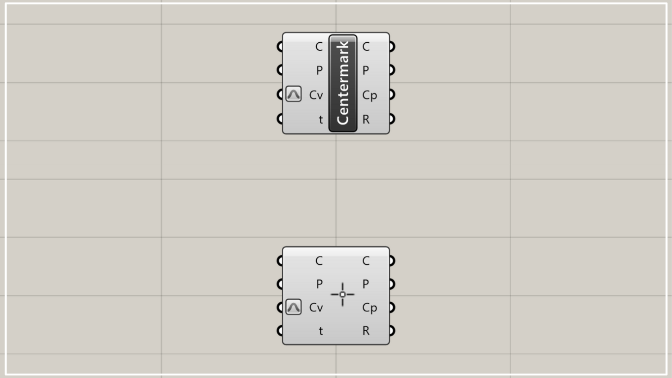
On the Grasshopper, it is represented by either of the two above.
Create center mark dimensions
Using Centermark allows you to create center mark dimensions.
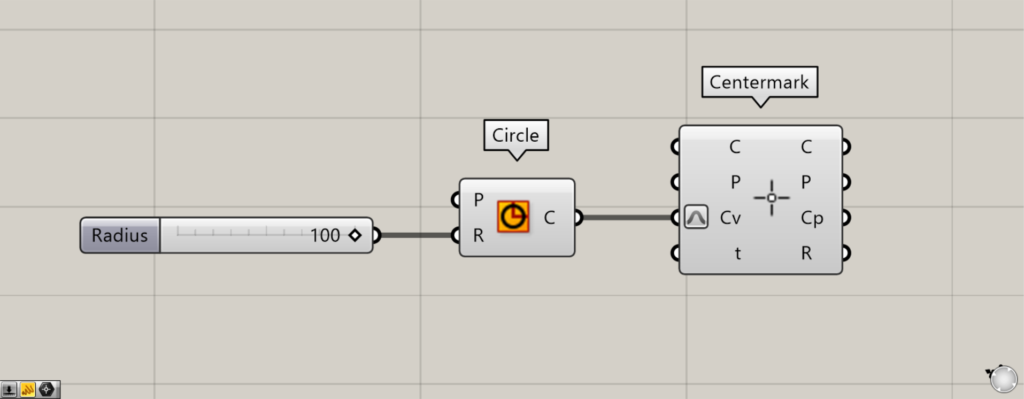
Components used: ①Circle ②Centermark
As a first example, let’s create a center mark dimension from a circle.
Enter 100 as the radius value into the Circle(R).
Then, a circle with a radius of 100 was created.
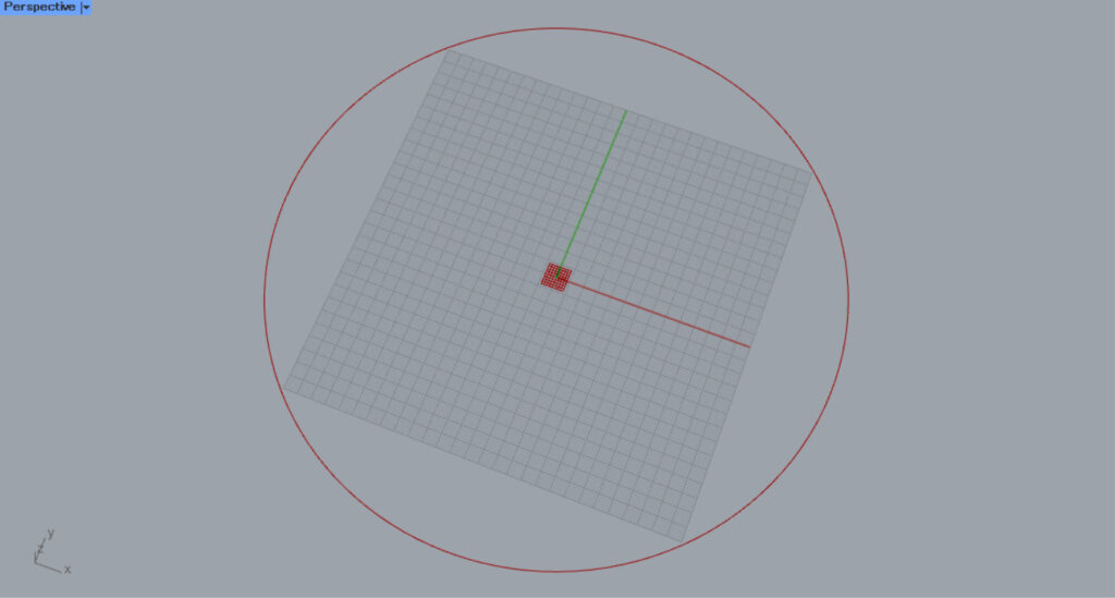
Next, connect the Circle to the Centermark(Cv).
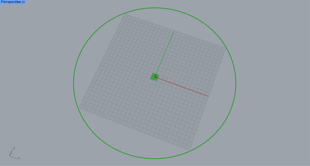
Then, a center mark dimension will be created at the center of the circle.
Zooming in reveals that a center mark dimension has been created.
In this way, you can create center mark dimensions in Centermark.
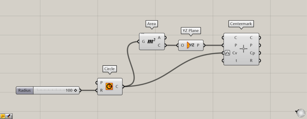
Additional Components: ①Area ②YZ Plane
The P terminal allows you to set plane.
This time, we’ll connect the YZ Plane to the Centermark(P).
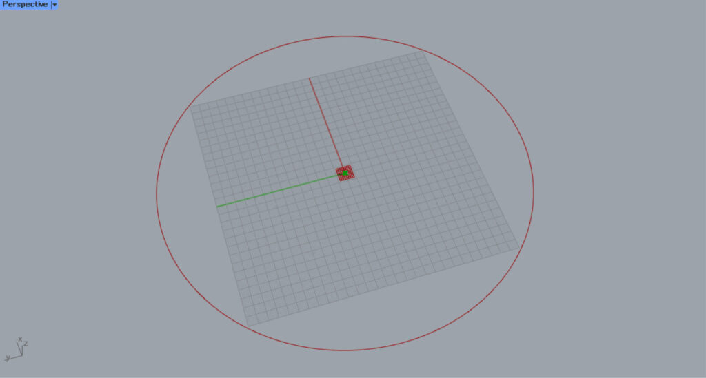
Connecting a Circle to an Area creates the center point of the circle from the Area(C).
Then, connect the Area(C) to the YZ Plane.
Then, a plane created from the Y and Z axes will be created at the center point of the circle.
Then, a center mark dimension is created on the plane.
In this case, the center mark dimension is created on the YZ-axis work plane, so it is created vertically.
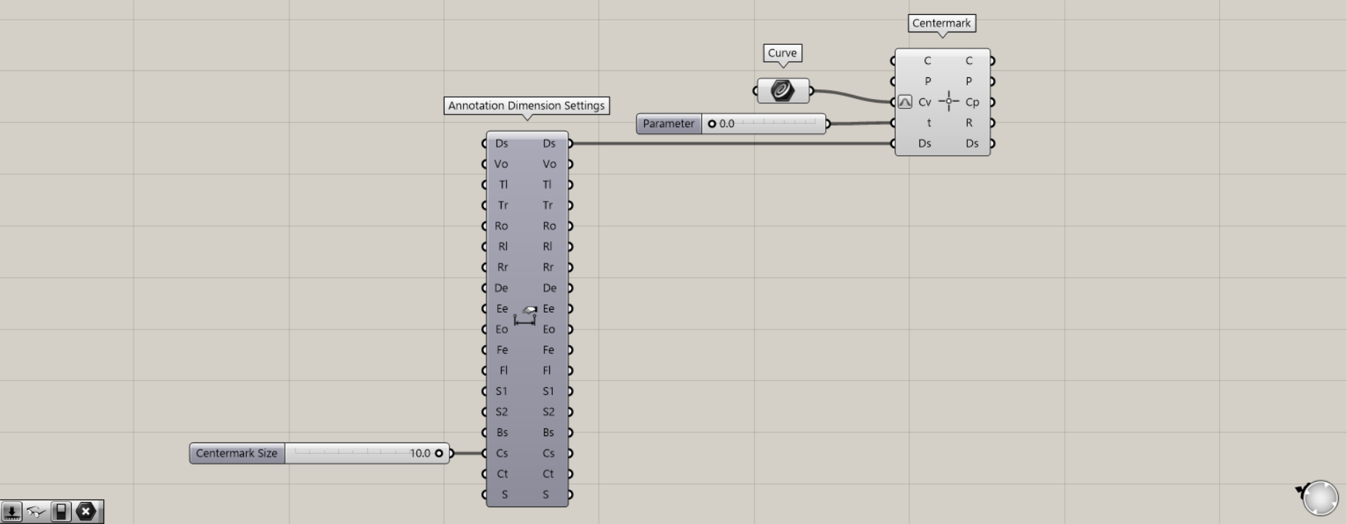
Next, let’s look at how to use the Centermark T-terminal.
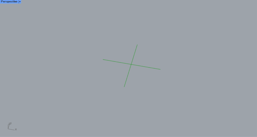
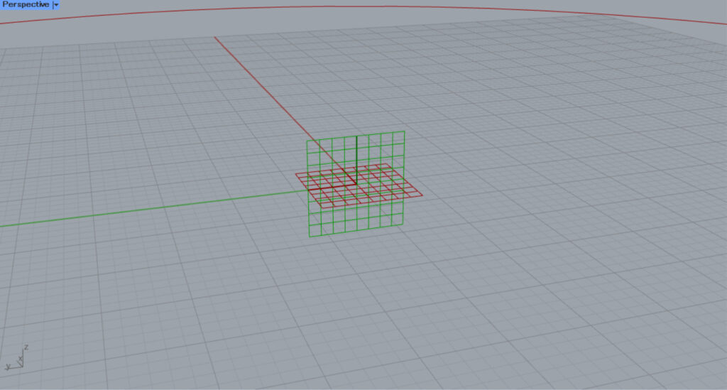
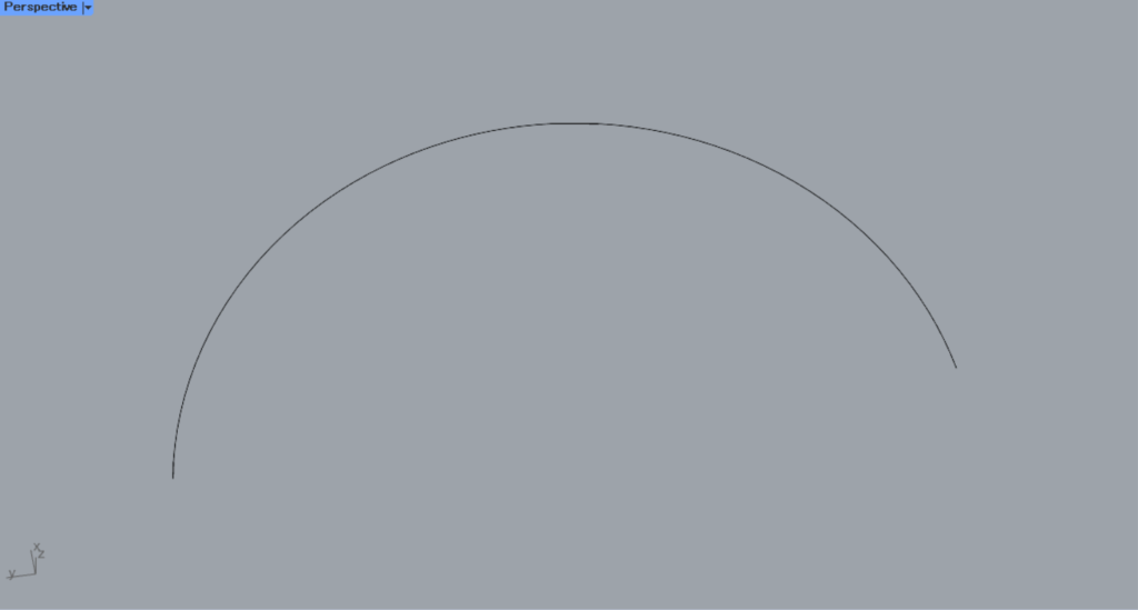
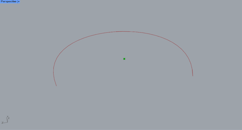
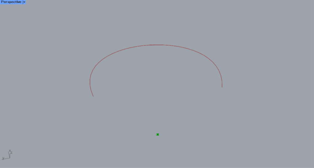
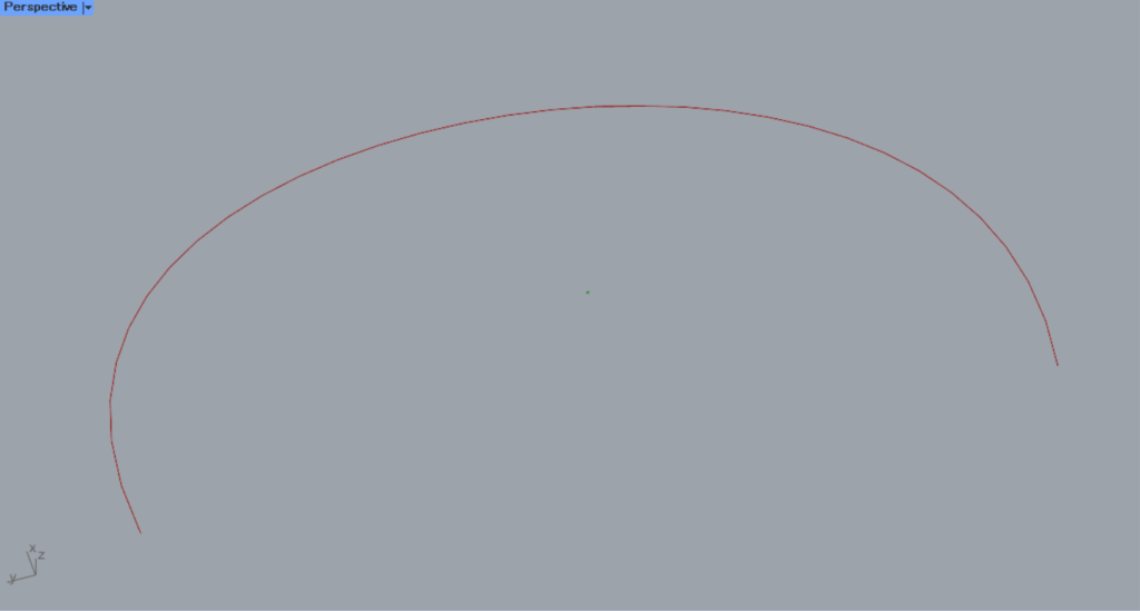
This time, we will use the curve on Rhino in the image above.
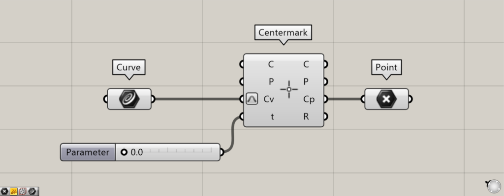
Components used: ①Curve ②Centermark ③Point
The T-terminal cannot be used in models with circular or other types of bilateral symmetry.
We will use asymmetric curves like the ones used this time.
By entering a value between 0 and 1.0 into the Centermark(t), you can adjust the position of the center mark dimension.
This time, to make the center mark dimensions easier to see, we’ve connected a Point to the Centermark(Cp) to display the point data.
When the terminal value is 0, it is located in this area.
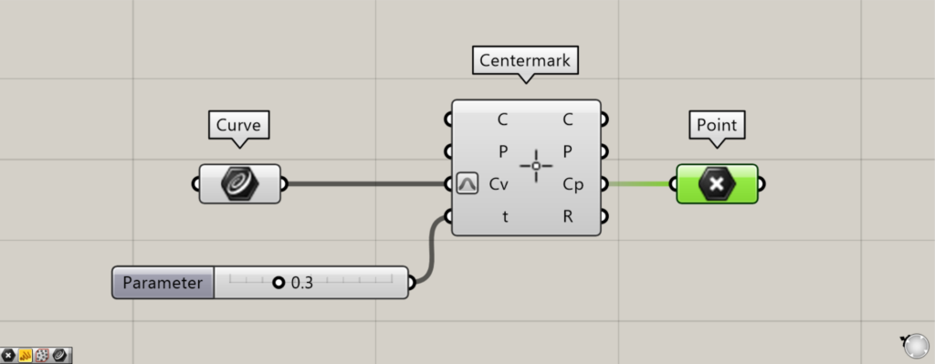
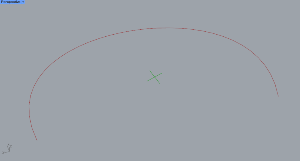
Let’s look at the case where the value is 0.3.
When the value is 0.3, the position has changed.
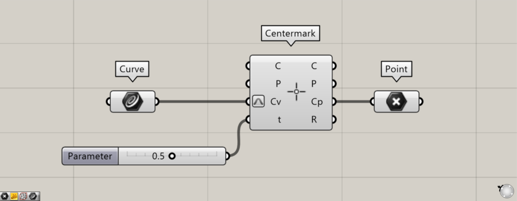
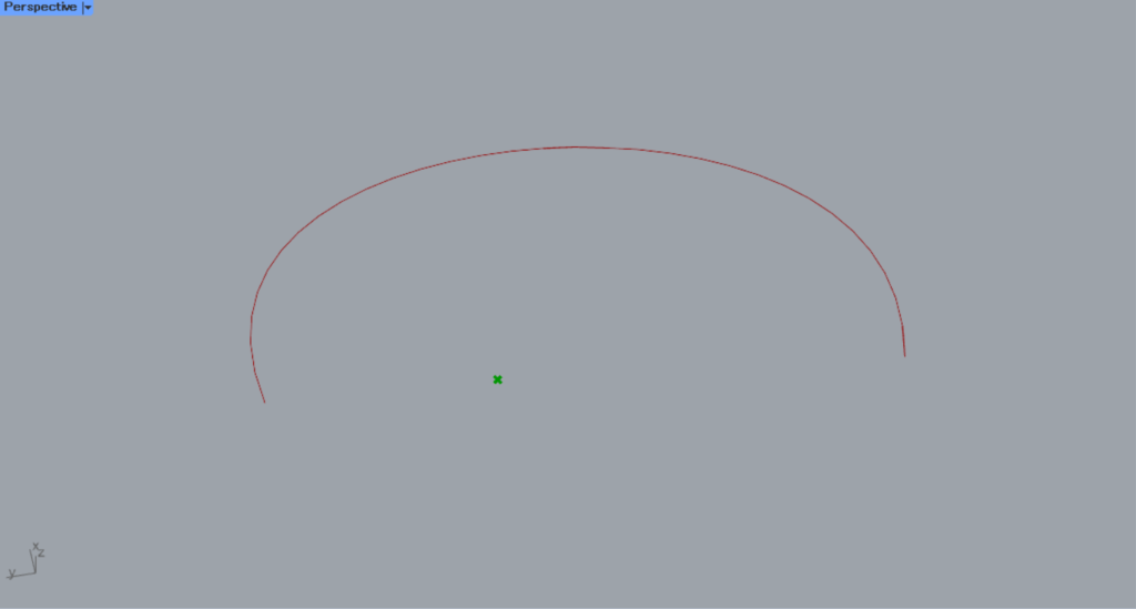
Let’s look at the case where the value is 0.5.
When the value is 0.5, the position changed further.
In this way, for asymmetric models, the position of the center mark dimension can be adjusted at the t terminal.
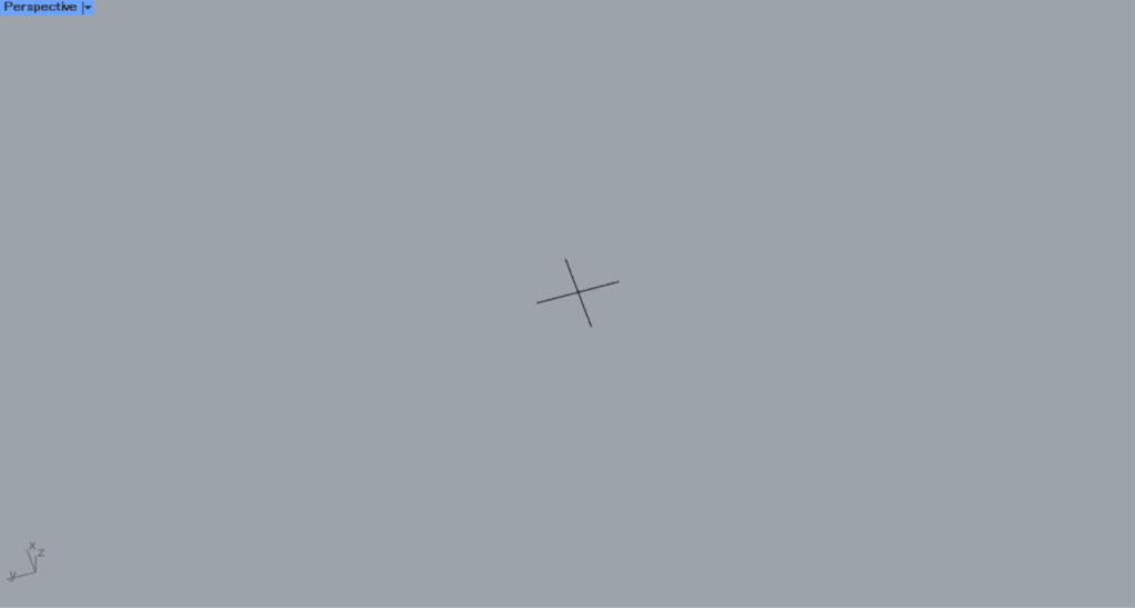
Next, let’s look at how to use the C terminal.
This time, we will use the center mark dimensions on Rhino in the image above for our explanation.
With the C terminal, you can acquire each data point that constitutes the existing center mark dimensions.
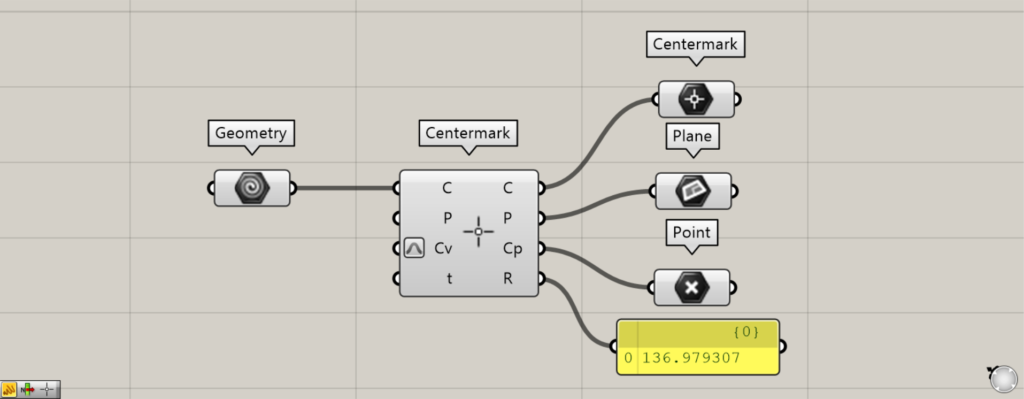
Components used: ① Geometry ② Centermark ③ Centermark ④ Plane ⑤ Point
Connect the existing center mark dimension on Rhino set in Geometry to the Centermark(C).
Then, data constituting the existing center mark dimensions will be output from the right-side terminal.
The C terminal outputs the data for the existing center mark dimensions that have been input.
Data for the plane, where existing center mark dimensions are created, is output from the P terminal.
Point data is output from the Cp terminal, representing the coordinates of the location where existing center mark dimensions are created.
The R terminal outputs the radius value.
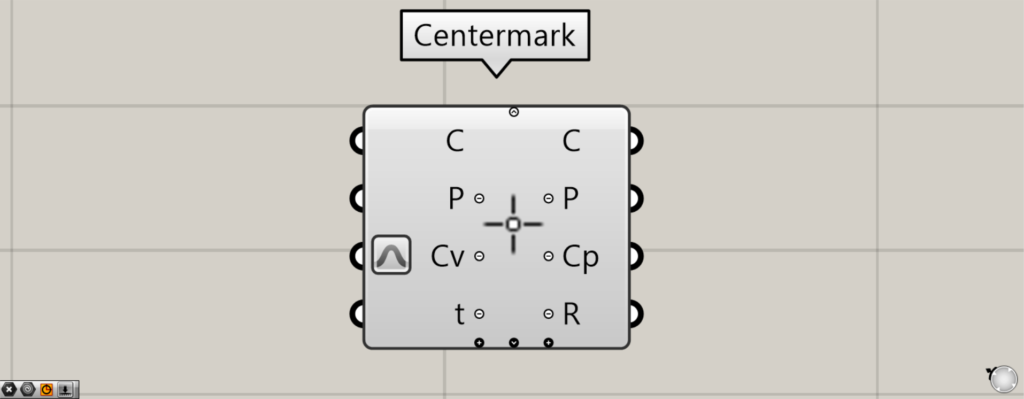
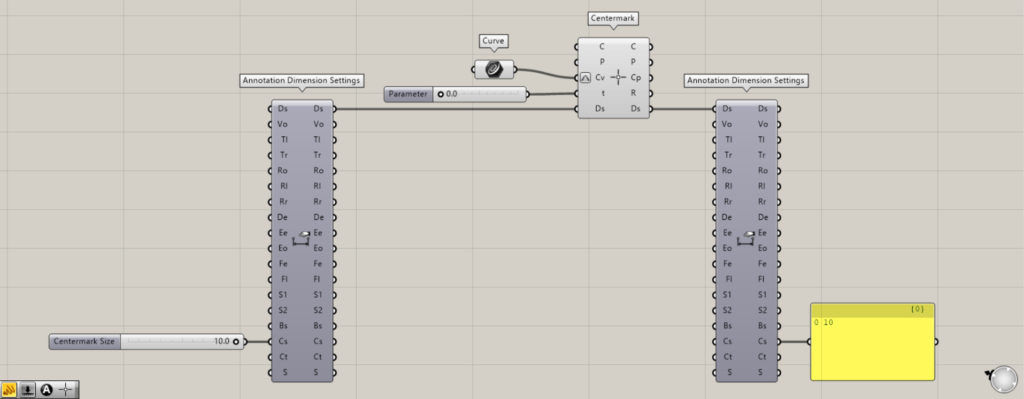
When you zoom in toward the Centermark component, arrow icons and plus and minus icons will appear.
Click the arrow or + icon at the bottom to display additional Ds terminals.
The Ds terminal allows you to configure detailed dimensional settings.
Additional Component: ① Annotation Dimension Settings
This time, we’ll change the scale of the center mark dimension using the Cs terminal in Annotation Dimension Settings.
This time, we entered several tens of values.
Next, connect the Ds terminal on the right side of the Annotation Dimension Settings to the Ds terminal of the Centermark.
This is the scale before the change.
After the change, the scale of the center mark dimensions has changed as shown here.
In this way, you can configure detailed settings for the center mark dimensions via the Ds terminal.
Data for detailed settings of the reflected center mark dimensions is output from the Ds terminal on the right side.
List of Grasshopper articles using Centermark component↓

Comment