![[Grasshopper]How to use the Evaluate Surface to obtain information at a specified position on the surface](https://iarchway.com/wp-content/uploads/2025/06/Evaluate-Surface.png)
This article explains how to use the Evaluate Surface to obtain information at a specified position on the surface.
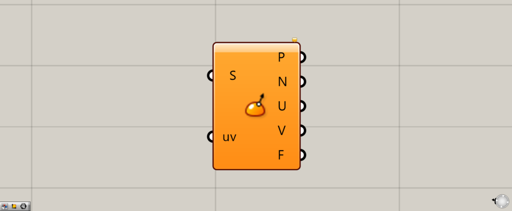
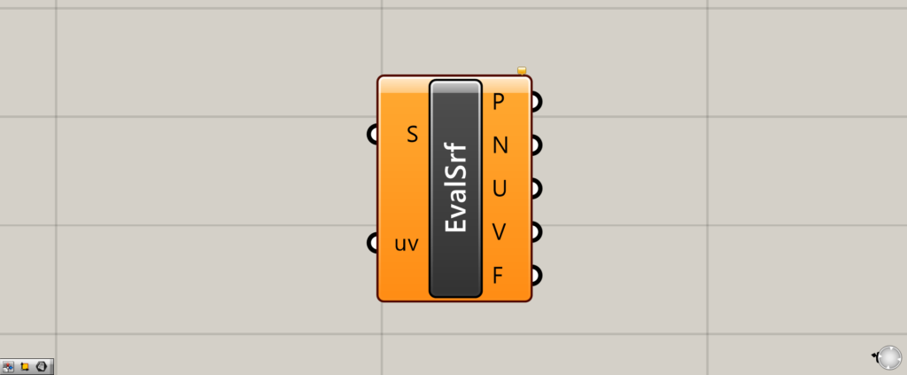
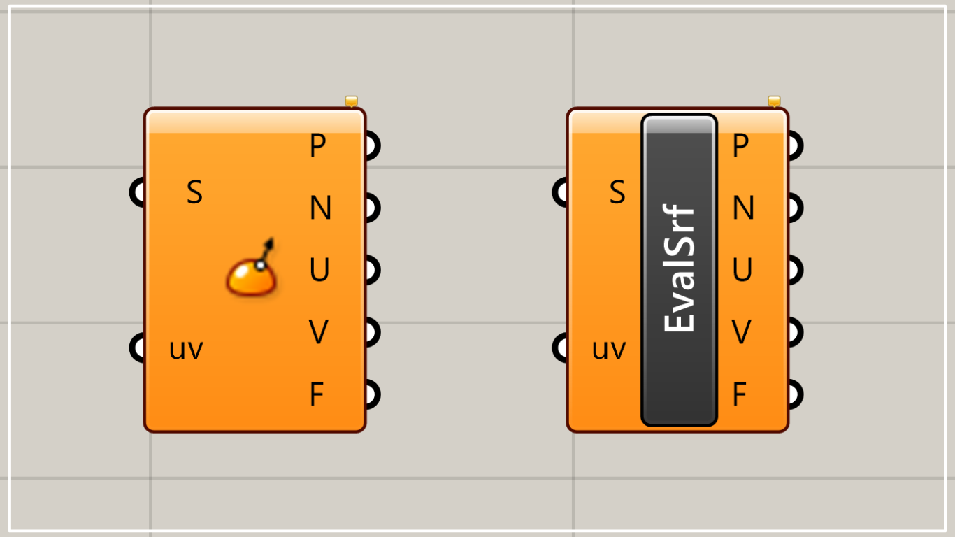
On the Grasshopper, it is displayed as either an icon or text.
Evaluate Surface Basics
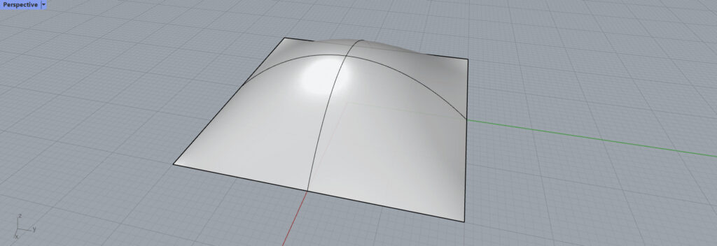
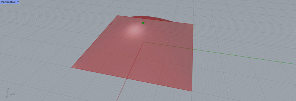
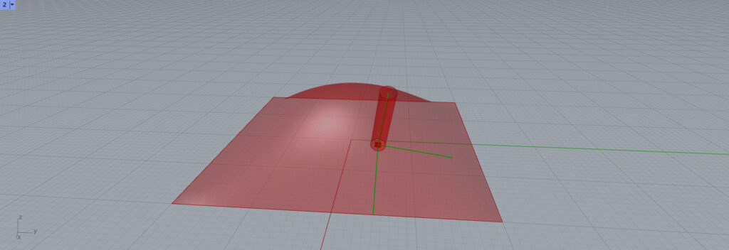
In this article, we will use this surface to explain how to use the Evaluate Surface.

Component used:①Surface ②Evaluate Surface ③MD Slider ④Construct Point
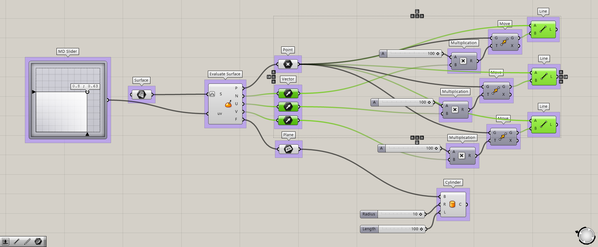
Here is the basic Evaluate Surface overall recipe.
Set to Reparameterize
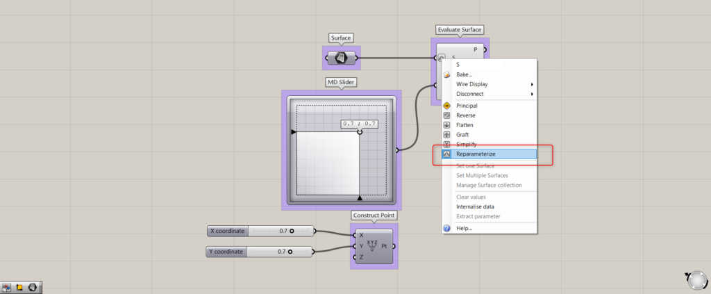
As a preliminary step, right click on the Evaluate Surface(S) and set it to Reparameterize.
This is because you will be able to represent the position of the surface with a value of 0~1 when performing operations such as positioning on the surface.
For example, the position of 500, the center of a surface with a width of 1000 mm, can be expressed as 0.5.
MD Slider and Construct Point
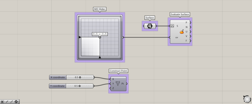
An MD Slider and a Construct Point are often used with the Evaluate Surface.
By moving these numbers from 0~0.1, you can get the position on the surface.
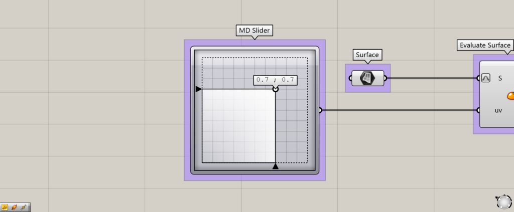
Connect the surface to be used to the Evaluate Surface(S) and the MD Slider or the Construct Point to Evaluate Surface(uv).
When using the Construct Point, set 0~1.0 to the Construct Point(X and Y).
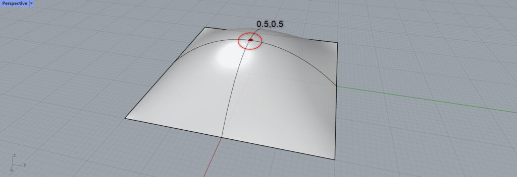
If the value is at 0.5,0.5, the red mark will be in the center of the surface.
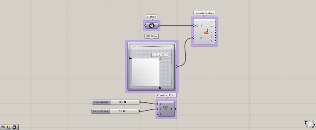
Now change the value to 0.7,0.7.
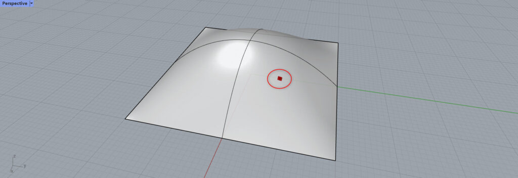
The red mark has then moved to a different location.
This location is the 0.7,0.7 position on this surface.
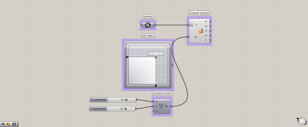
The same result is achieved with Construct Point instead of MD Slider.
Information output from Evaluate Surface
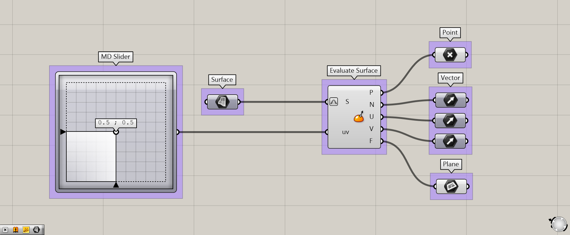
Component used:①MD Slider ②Surface ③Evaluate Surface ④Point ⑤Vector ⑥Plane
There are three main types of information output from Evaluate Surface.
They are point information, vector information, and plane information.
Point
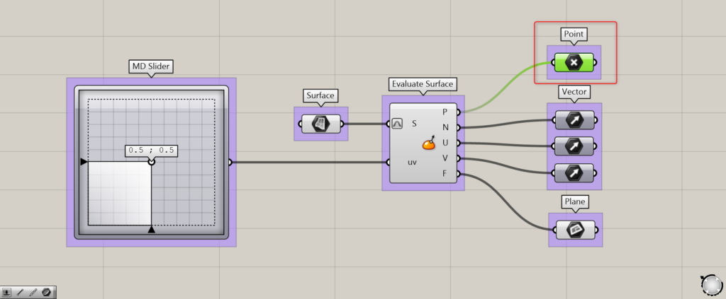
From the Evaluate Surface(P), a point is created at the position specified by the MD Slider or the Construct Point.
Thus, you can see that a point is created.
Vector
There are three types of vector information output from Evaluate Surface.
Normal vector
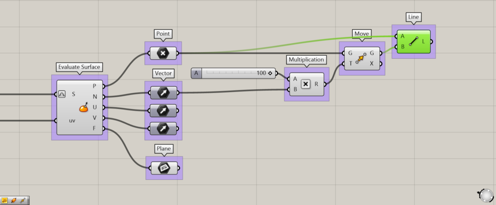
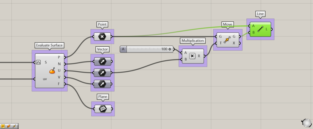
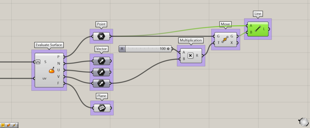
Additional component:①Multiplication ②Move ③Line
The first is the normal vector (Normal) output from the Evaluate Surface(N).
In this case, it is safe to understand that it is a vector from one point on the surface to a vertical direction.
To check the normal vector this time, we have created a line by moving the point just created with the normal vector of the Evaluate Surface(N).
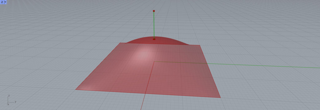
When a normal vector was used, the line extended in the direction of the normal vector.
we changed the position information on the surface to 0.7,0.7.
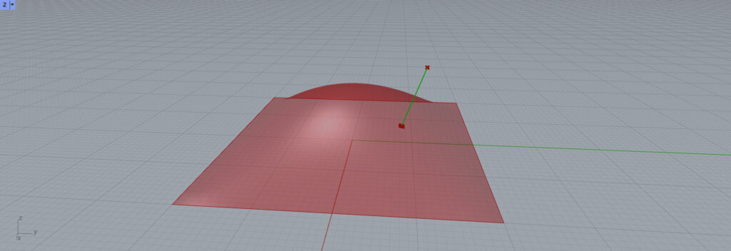
At the 0.7,0.7 position, it stretched like above.
UV Vector
The remaining two vectors are the U and V vectors.
Let’s start with the U vector.
The vector of the program that creates the line just described is made into a U-vector.

Then, the line extended horizontally this time.
Now run it with V vector.

Then, the line now extends in another horizontal direction.
Thus, a UV vector is a horizontal vector of a single point on a surface.
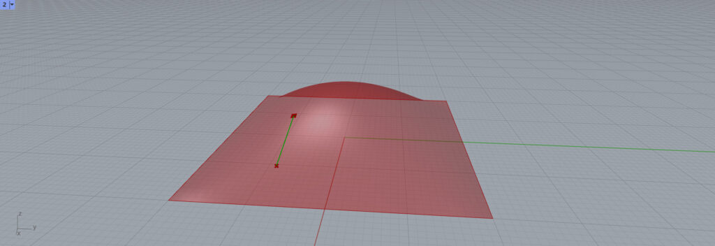

For other locations, a horizontal line was created on such surfaces.
Plane
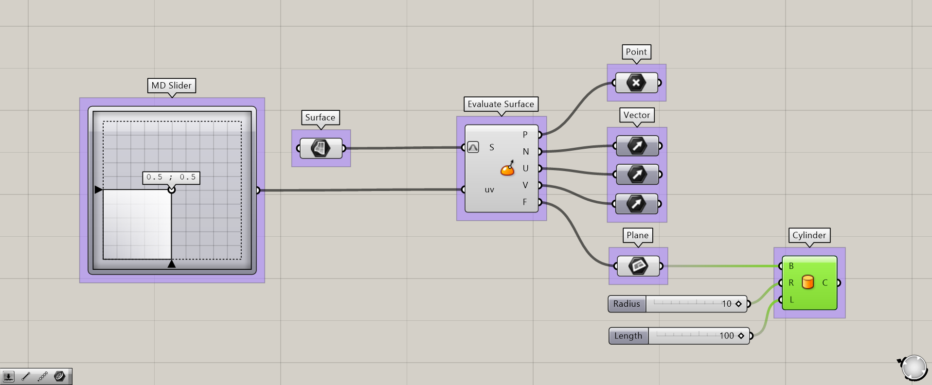
Additional component:①Cylinder
The last one is about plane.
It is extracted from the Evaluate Surface(F).
This represents the plane of a single point on the surface.
Simply put, think of it as a fusion of the normal vector and UV vector from earlier.
In this case, we will use a Cylinder and the plane to create a cylinder.
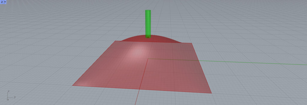
Thus, a cylinder is created.
Since the plane already has information on normal and UV vectors, it can be used with components such as Cylinder that do not require vectors to be specified.
Let’s look at the three vectors.
Then we see three lines at the location of the cylinder.
We can now see that the plane consists of three vectors.
List of Grasshopper articles using the Evaluate Surface component↓

Comment