
![[Grasshopper] How to use Leader to create and edit leader lines](https://iarchway.com/wp-content/uploads/2026/01/Leader-1.png)
This article explains how to use Leader to create and edit leader lines.
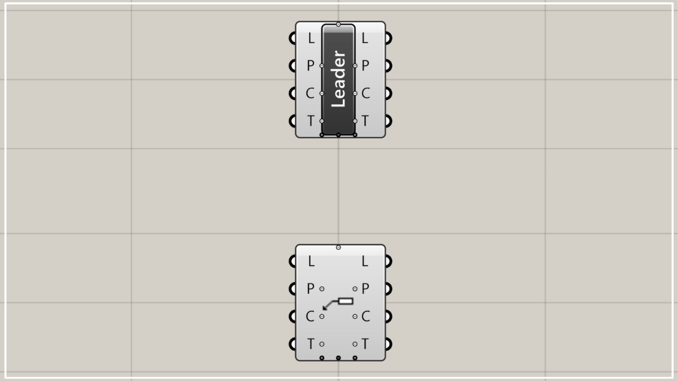
On the Grasshopper, it is represented by either of the two above.
Create a leader line
Using Leader, you can create leader lines.
This time, we’ll explain using lines on Rhino.
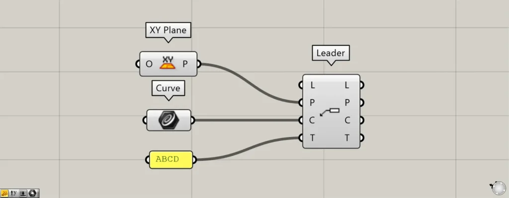
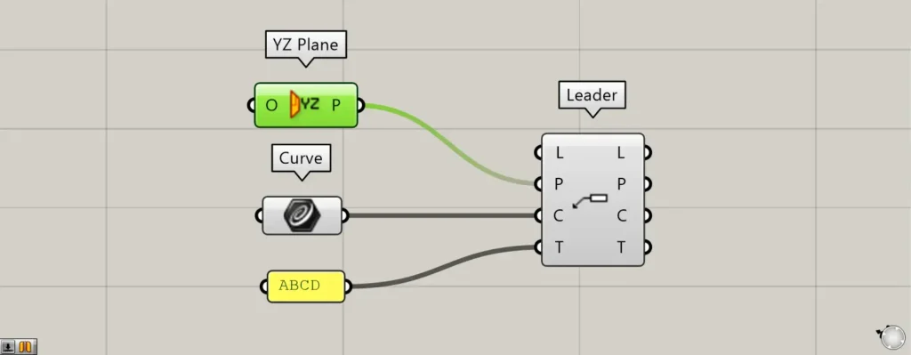
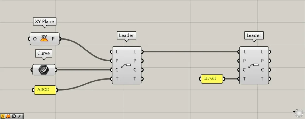
Components used: ① XY Plane ② Curve ③ Leader
Connect the information about the plane where the leader line is created to the Leader(P).
This time, because the XY Plane is connected, the extension lines are created on the plane formed by the X and Y axes.
Then, set the line on rhino in the Curve.
Then connect the Curve to the Leader(C).
Enter the texts you want to display into the Leader(T).
This time, we are entering ABCD.
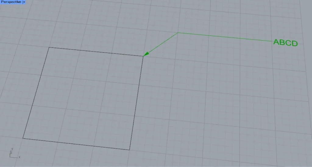
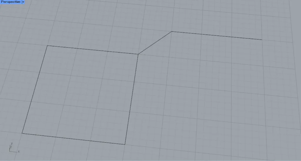
Then, the leader line was created like this.
Additional Component: ① YZ Plane
We’ll try changing the plane connected to the Leader(P).
This time, we’ll connect the YZ Plane, which creates a plane from the Y and Z axes.
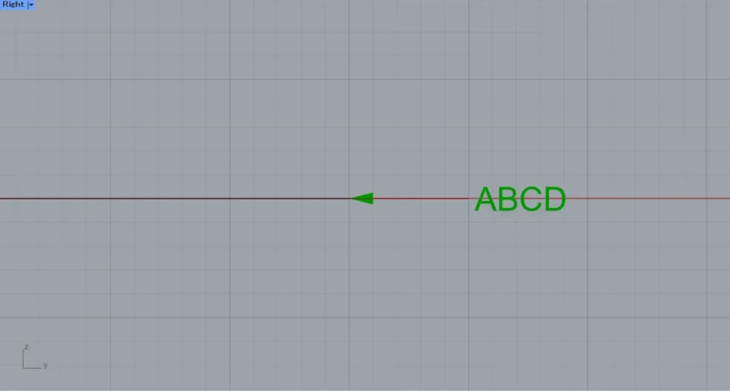
Then, the plane where the lead-out line is created changed.
Acquire and edit information constituting existing leader lines
You can also retrieve and edit the information that makes up existing existing leader.
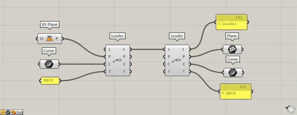
Additional Component: ①Plane
Connect the existing leader line to the new Leader(L).
Then, you can obtain the information that makes up the existing leader lines.
The acquired leader lines can be obtained from the Leader(L) on the right side.
From the Leader(P) on the right, you can obtain the plane from which the leader line is created.
From the Leader(C) on the right, you can obtain the wire information used to create the leader line.
Text information used can be retrieved from the Leader(T) on the right side.
You can also edit the information that makes up existing leader lines.
With the existing leader line connected to the L terminal, enter the information for the P, C, and T terminals.
This time, we entered new text information—EFGH—into the Leader(T).
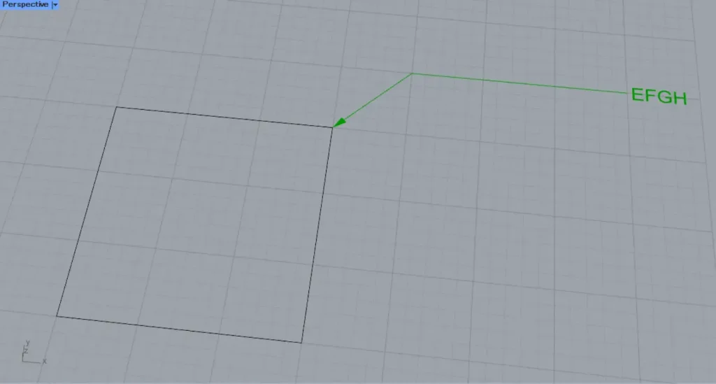
Then, we were able to edit only the text information.
In this way, you can edit part of the original leader line.
Configure the detailed settings
You can also configure the detailed settings for the leader lines.
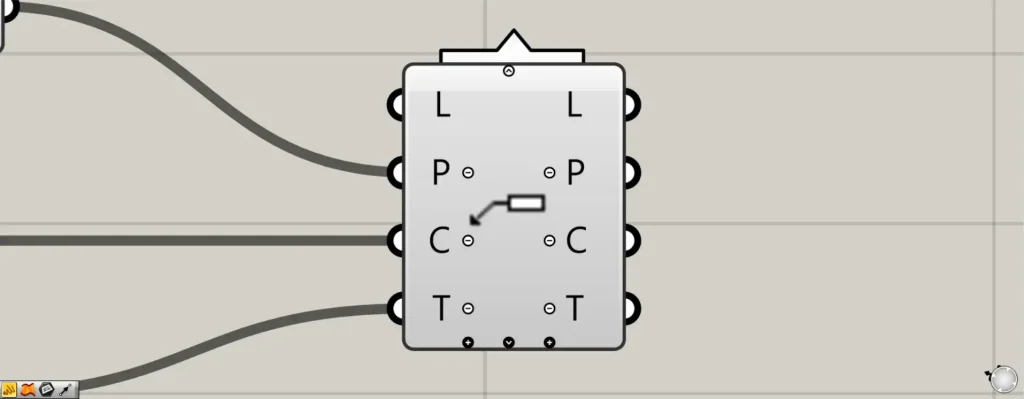
When you zoom in on the Leader component, icons such as +, -, and arrows appear.
Pressing the black + or arrow at the bottom will display new terminals.
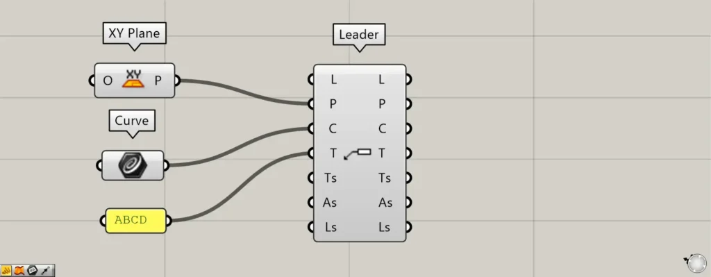
When all terminals are displayed, the Ts, As, and Ls terminals will appear.
The Ts terminal allows detailed text settings.
On the As terminal, you can configure the arrow’s detailed settings.
The Ls terminal allows detailed configuration of the lead wires.
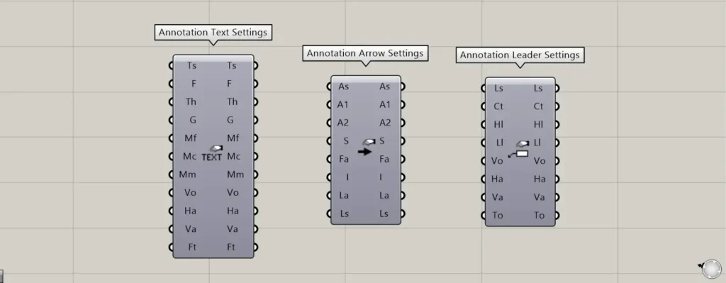
For the Ts terminal, use the Annotation Text Settings.
For the As terminal, use the Annotation Arrow Settings.
For the Ls terminal, use the Annotation Leader Settings.
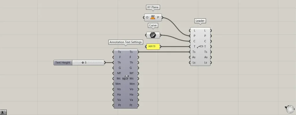
As an example this time, we’ll connect Annotation Text Settings to the Ts terminal and configure the text details.
Enter the font size value in the the Annotation Text Settings(Th).
This time, enter 3.
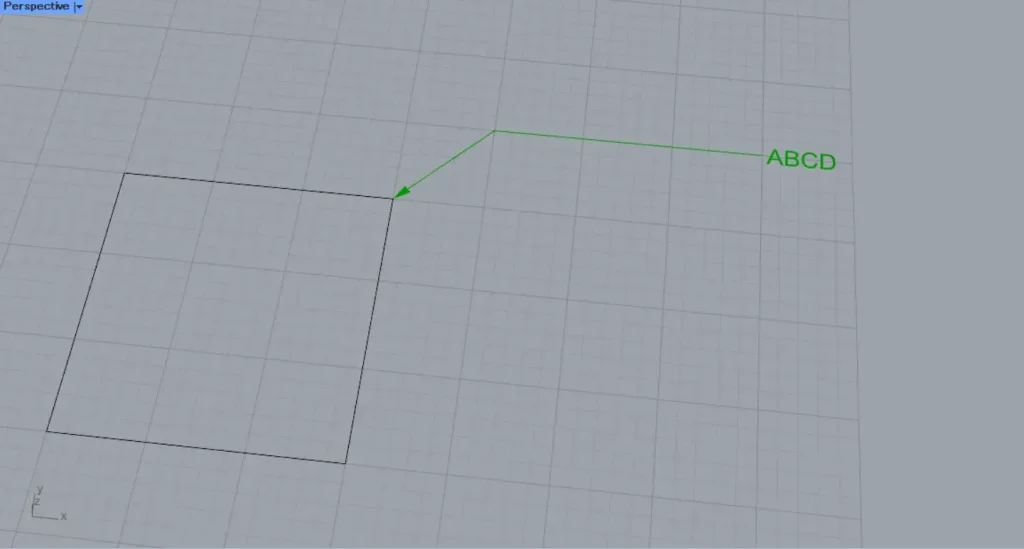
This is the original font size.
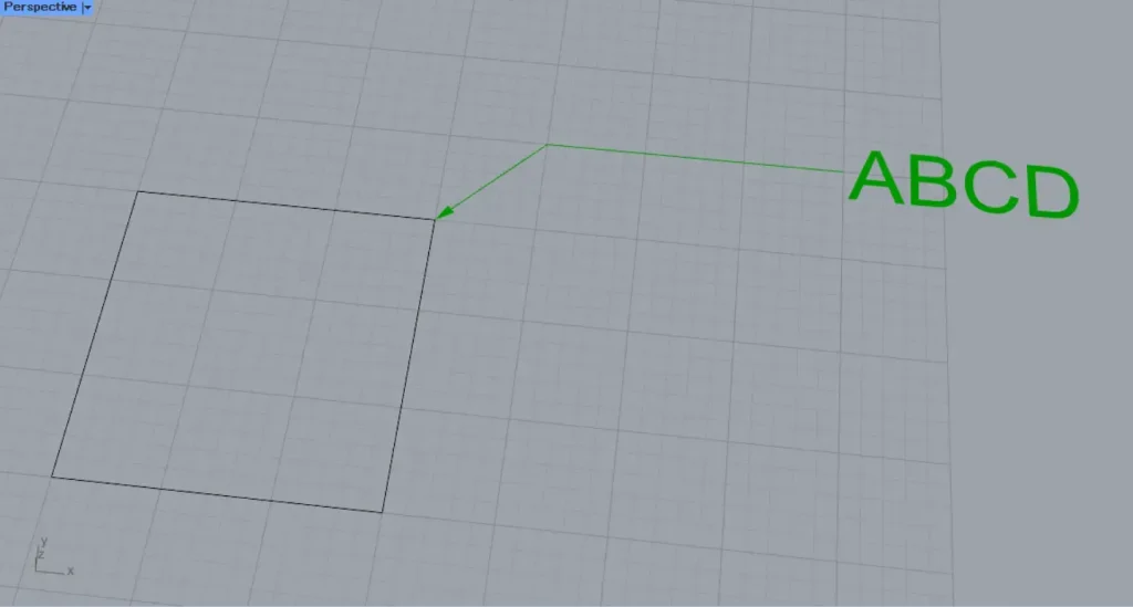
After setting, the font size has changed.
In this way, you can also configure the detailed settings for the leader lines.
List of Grasshopper articles using Leader component↓

Comment