
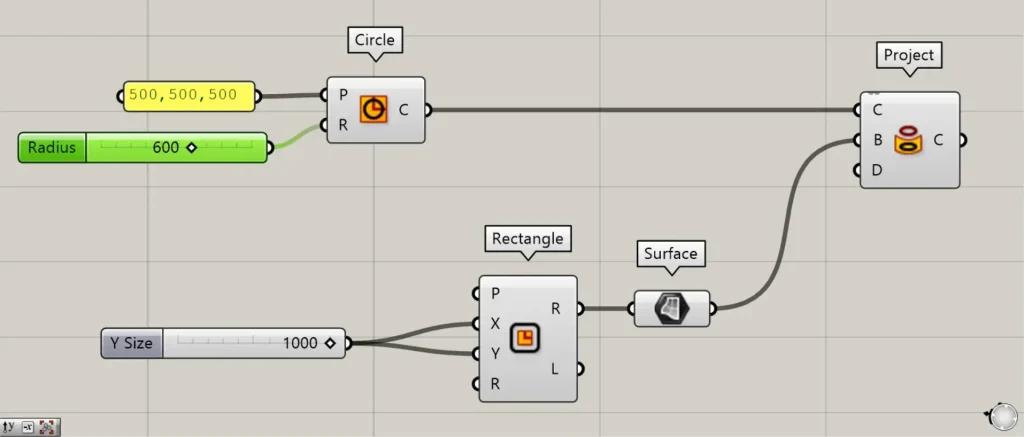
![[Grasshopper] How to use Project to project curves onto surfaces and breps](https://iarchway.com/wp-content/uploads/2026/01/Project.png)
This article explains how to use Project to project curves onto surfaces and breps.
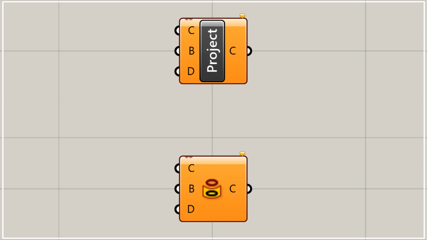
On the Grasshopper, it is represented by either of the two above.
Project curves onto surface/Brep models
Using Project, you can project curves onto surfaces and Brep models.
Please note that there is another Project with the same name, which is a component for projecting objects onto planes.
For more details on the other Project, please refer to the article above.
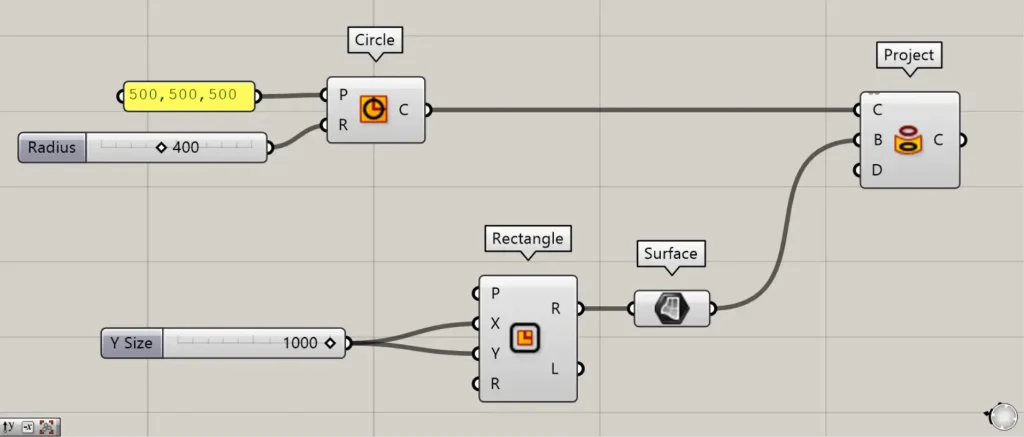
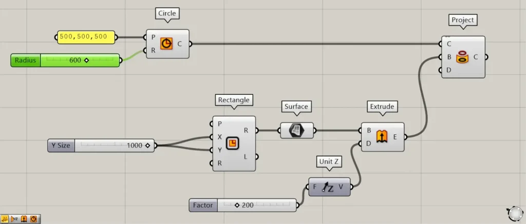
Components used: ①Circle ②Rectangle ③Surface ④Project
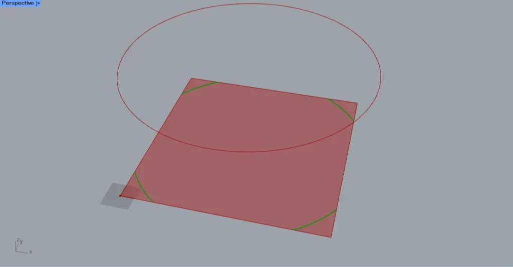
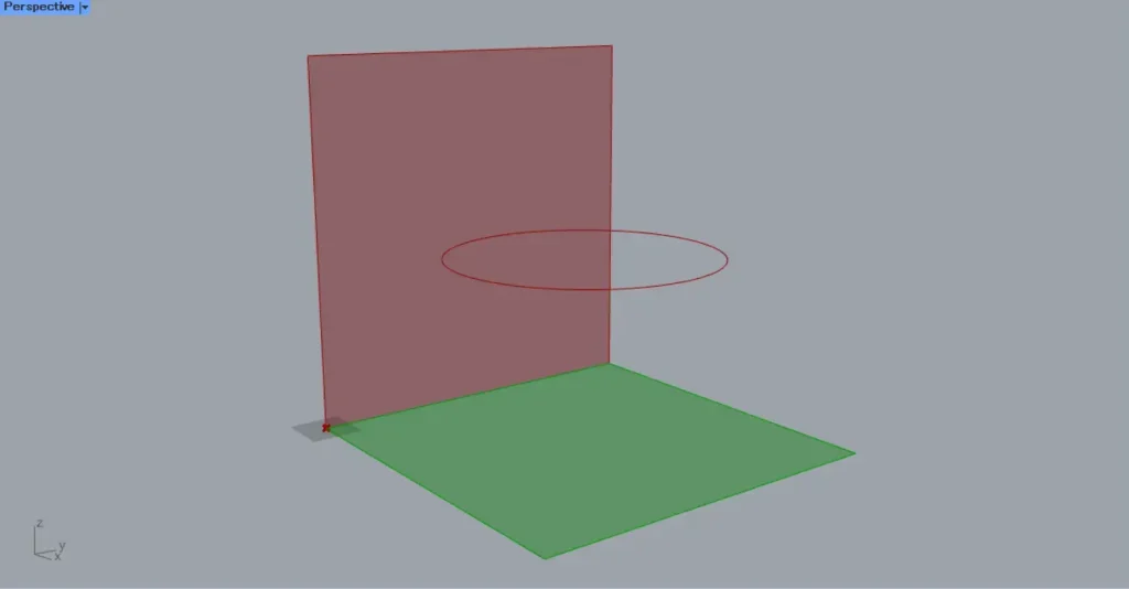
As an example, let’s project the curve data of a circle onto a surface.
Enter the coordinate values into the Circle(P).
This time, we entered 500,500,500.
Then, enter the radius value into the Circle(R).
This time, we entered 400.
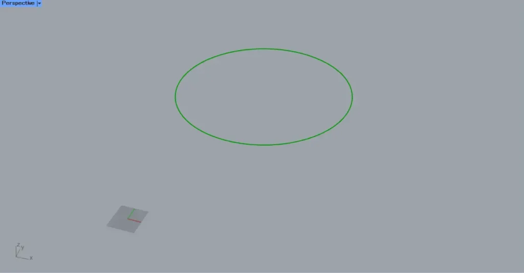
Then, as shown in the image above, the curve data for the circle was created at the specified position.
Next, enter the numerical value for the length of one side into the Rectangle(X and Y).
This time, we are entering 1000.
Then, a 1000×1000 square line data set will be created.
Next, connect the Rectangle(R) to the Surface.
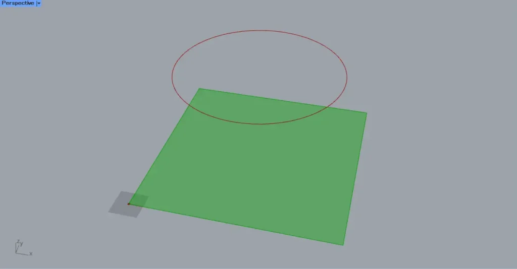
Then, the square line data was converted into a surface.
Then connect the Circle to the Project(C).
Then connect the Surface to Project(B).
Then, as shown in the image above, the curve data of the circle was projected onto the square surface.
If no vector is set for the Project(D), it will be projected along the Z-axis by default.
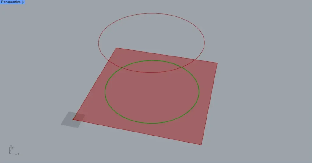
Increase the radius value of the Circle(R) so that it extends beyond the square.
In that case, only the portion within the square will be projected, as shown in the image above.
When projecting onto a Brep model
Let’s look at the case of projecting onto a 3D Brep model.
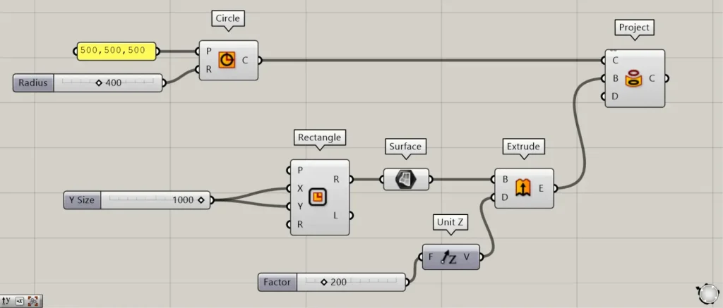
Additional Components: ①Unit Z ②Extrude
Enter the value to be pushed into Unit Z.
This time, we are entering 200.
Next, connect Unit Z to the Extrude(D).
Next, connect the Surface to the Extrude(B).
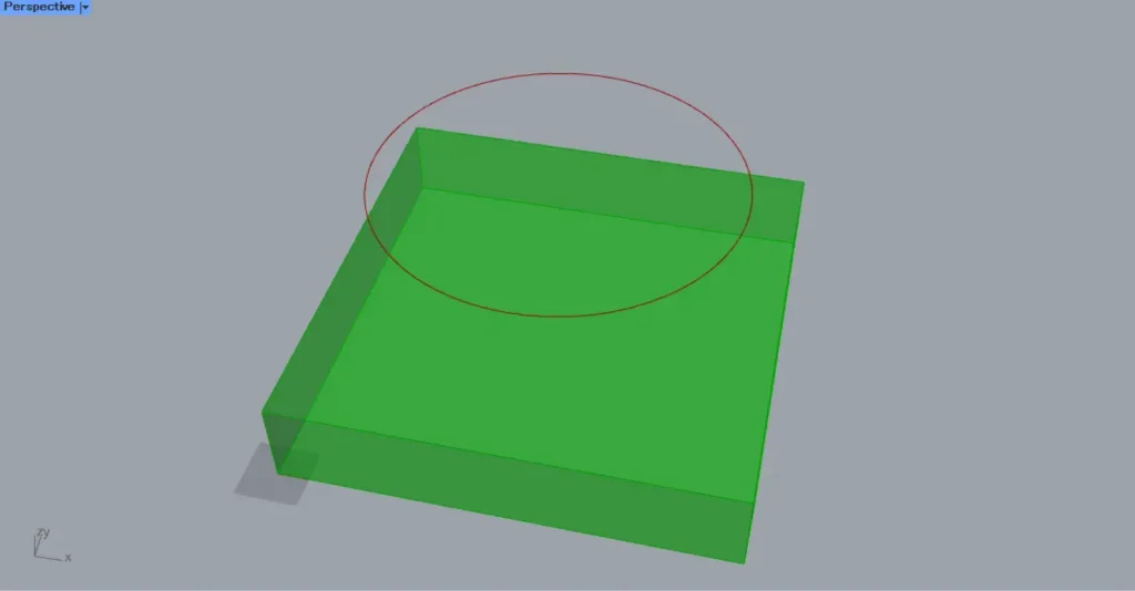
Then, the surface was extruded, becoming a three-dimensional Brep object.
Then connect the Extrude to the Project(B).
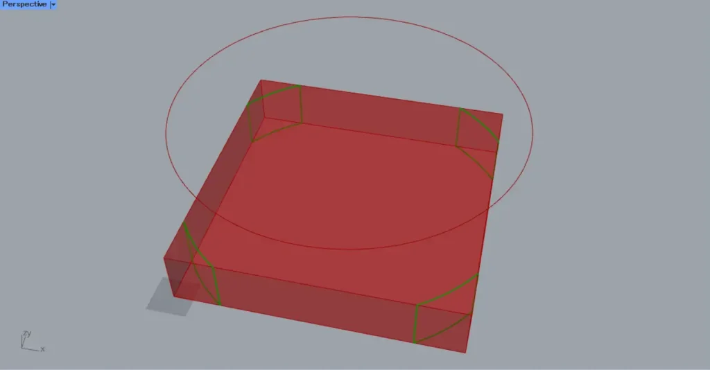
Then, as shown in the image above, curves were projected onto the 3D Brep object as well.
In this case, curves are projected onto the top and bottom faces of the cube.
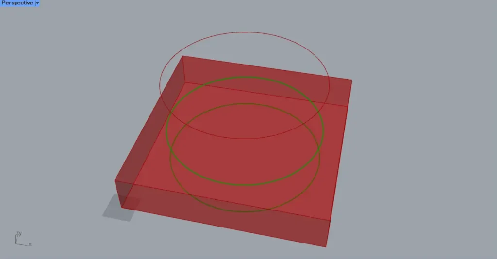
In this case too, let’s try increasing the radius value of the circle.
In this case as well, only the portion projected within the cube can be obtained.
In the image above, you can see that curve data exists not only on the top and bottom faces of the cube, but also on its side faces.
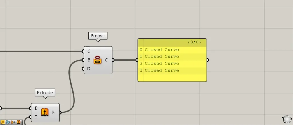
If curves are connected after projection, they will remain connected.
In the case of the previous image, the four edges are connected, forming a closed line data set.
Specify the projection direction
By connecting vector data to the Project(D), you can also specify the projection direction.
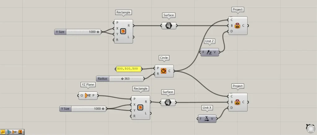
Additional Components: ① YZ Plane ② Unit X
Prepare two sets each of Rectangle and Surface.
Connect the YZ Plane to the Rectangle(P).
Then, a square is also created on the plane formed by the Y-axis and Z-axis.
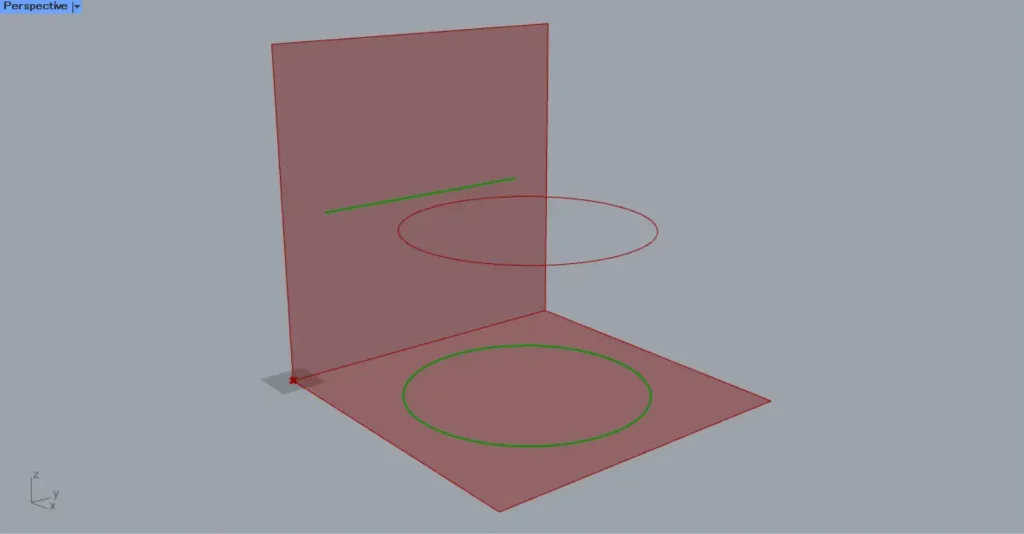
And to the D terminal of the first project, we connect Unit Z to provide the Z-axis vector.
The D terminal of the second project is connected to Unit X, providing the X-axis vector.
Then, as shown in the image above, the projection direction changed.
In the vertical direction of Unit Z, as before, a circle is projected.
Unit X projects the circle from directly sideways, so it appears as a single line.
List of Grasshopper articles using Project component↓

Comment