![[Grasshopper] How to Use SubD from Mesh to Create SubD from a Mesh](https://iarchway.com/wp-content/uploads/2026/01/SubD-from-Mesh.png)
This article explains how to use SubD from Mesh to Create SubD from a Mesh.
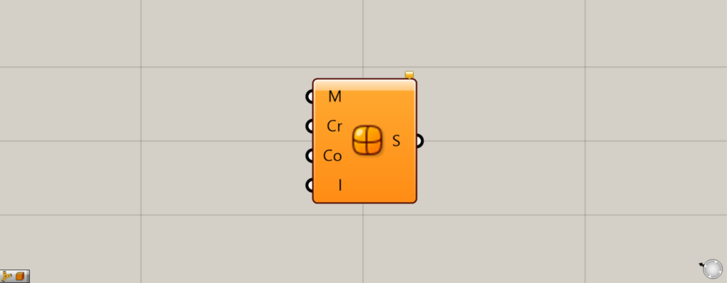
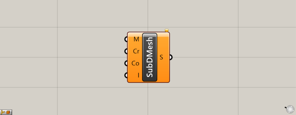
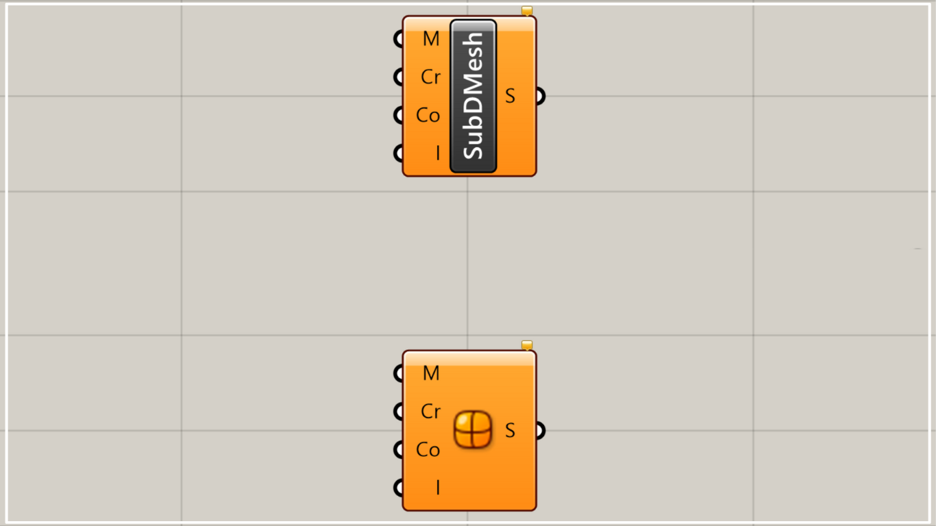
On the Grasshopper, it is represented by either of the two above.
Create SubD from a mesh
Using SubD from Mesh allows you to create a SubD model from a mesh.
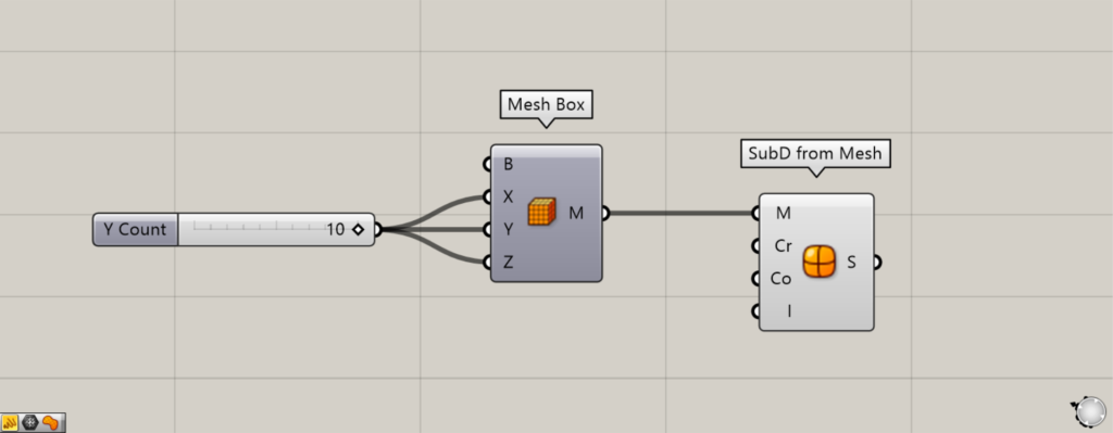
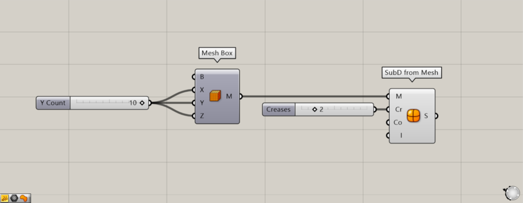
Components used: ① Mesh Box ② SubD from Mesh
First, as an example, let’s create a SubD from a mesh box.
Enter the number of mesh faces in each direction into the Mesh Box(X, Y, and Z).
This time, since 10 is entered, a mesh box with 10×10×10 mesh faces will be created.

Next, connect the Mesh Box to the SubD from Mesh(M).
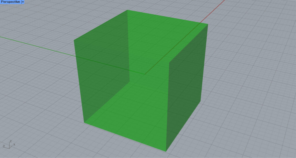
Then, a SubD object was created from the Mesh box.
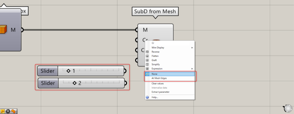
The Cr terminal allows you to specify creases (model edges).

Connect 1 or right-click the Cr terminal and set it to None.

Then the edges will become smooth.
Connect 2 or right-click the Cr terminal and set it to At Mesh Edges.
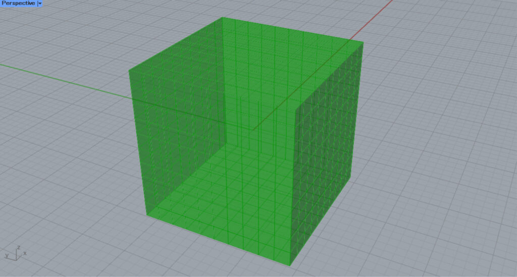
Then it will look like the original mesh edges.
Additional Component: ① Boolean Toggle
Since the Co terminal is difficult to understand in 3D, we’ll skip the explanation for now.
By setting the I terminal, you can specify whether the mesh should pass through the vertices.
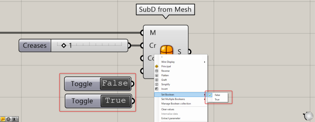
Specify True or False for the I terminal.
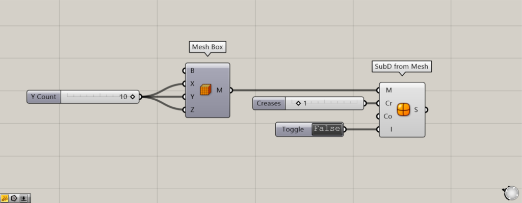
Connect a False Boolean Toggle to the I terminal, or right-click the I terminal and select False.
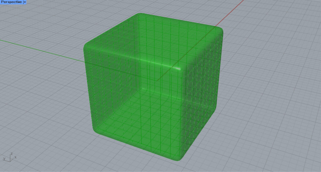
This results in a shape that does not pass through the original mesh’s vertices.

Connect a True Boolean Toggle to the I terminal, or right-click the I terminal and select True.

This results in a shape that passes through the vertices of the original mesh.
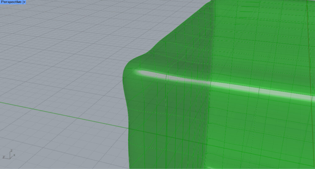
Zooming in reveals that it passes through the original mesh’s vertices.
Finally, let’s take a look at the Co terminal.
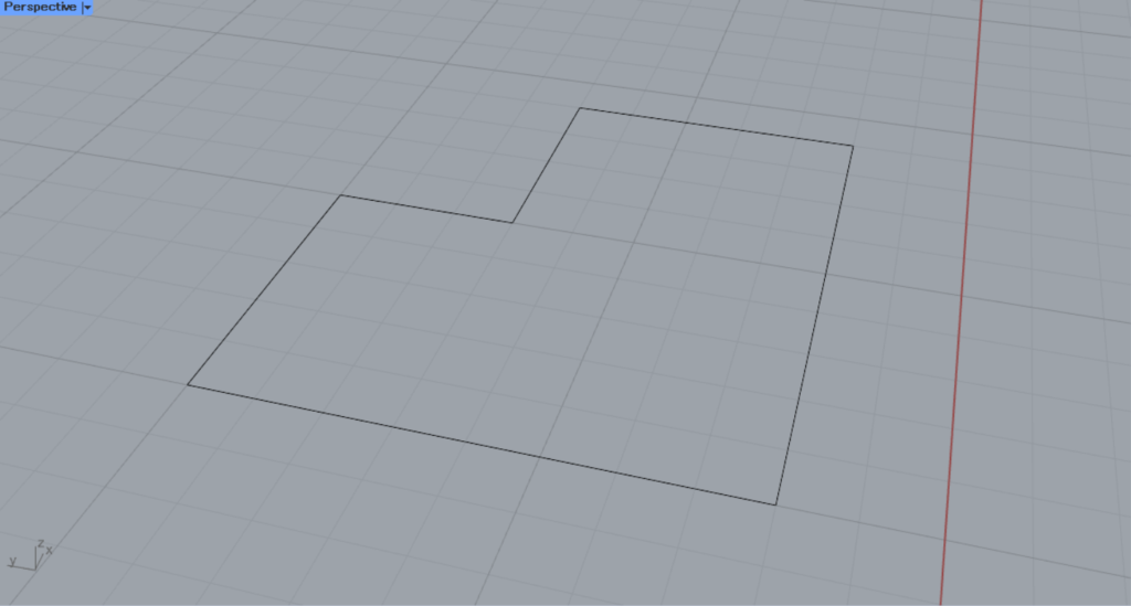
This time, I will explain using a closed line on Rhino, as shown in the image above.
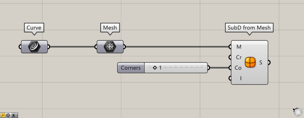
Components used: ①Curve ②Mesh ③SubD from Mesh
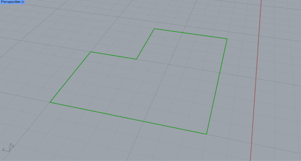
Set the line on Rhino in the Curve.
Then connect the Curve to the Mesh.
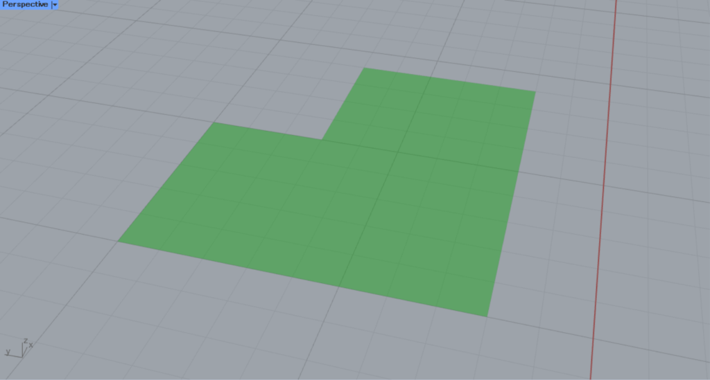
Then it will be converted from a line to a mesh.

Next, connect the Mesh to the SubD(M) from Mesh.
Then it will be converted from mesh to SubD.
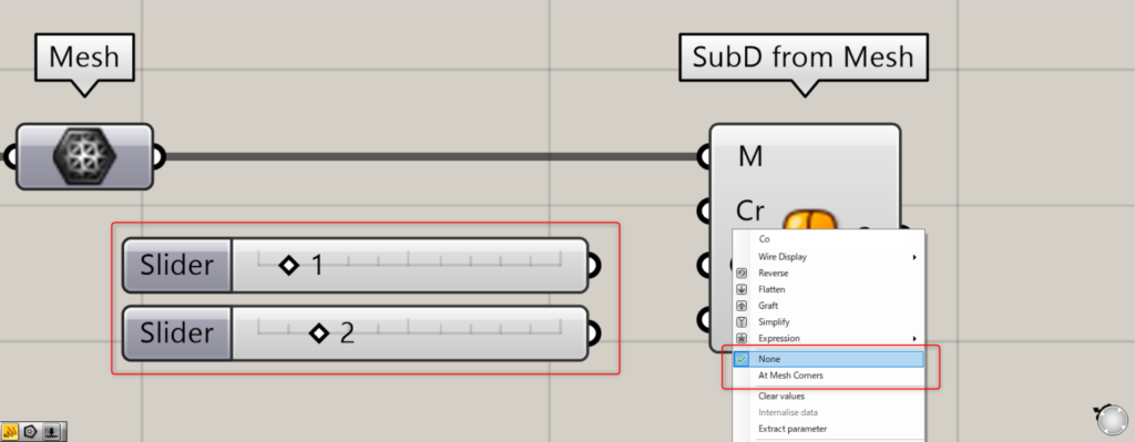
For the Co terminal, you can specify whether the corners should be positioned at the original mesh face corners.

Enter 1 into the Co terminal, or right-click the Co terminal and select None.
Then you’ll see that the corners are not in the original positions of the mesh faces.
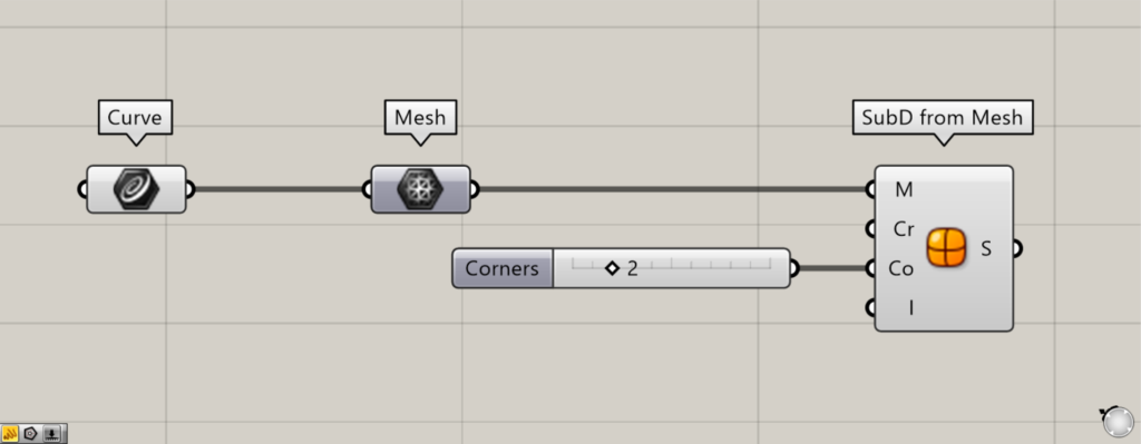
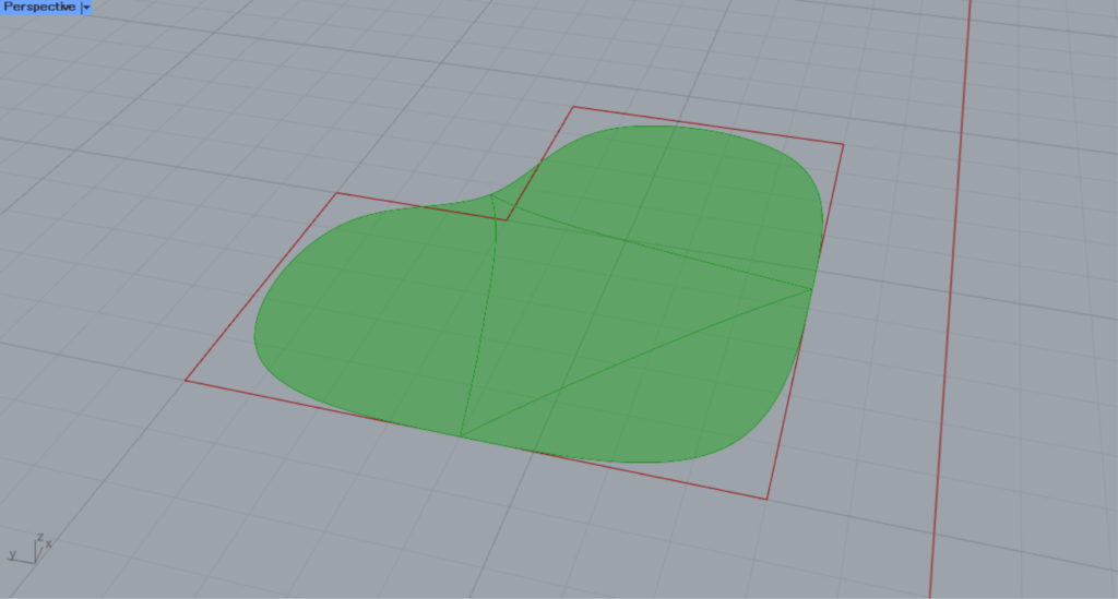
Enter the number 2 into the Co terminal, or right-click the Co terminal and select At Mesh Corners.
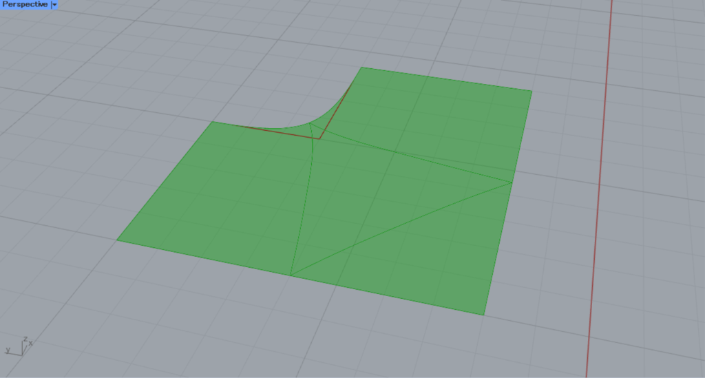
Then you can see that the corner has moved to the original position of the mesh face’s corner.
List of Grasshopper articles using SubD from Mesh component↓

Comment