
![[Grasshopper]ブラック・ホワイトホールをイメージした空間[データも配布]](https://iarchway.com/wp-content/uploads/2025/02/eyecatch_web-1.jpg)
This article describes Design inspired by a Black hole and a White hole using Grasshopper.
The Grasshopper file used in this project is also available for download.
Video
Model Images
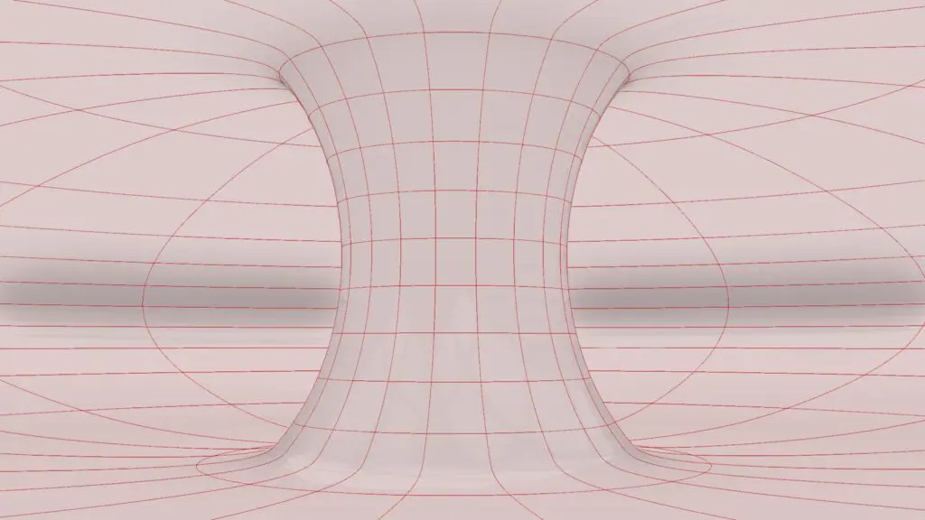
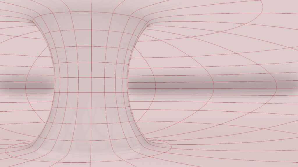
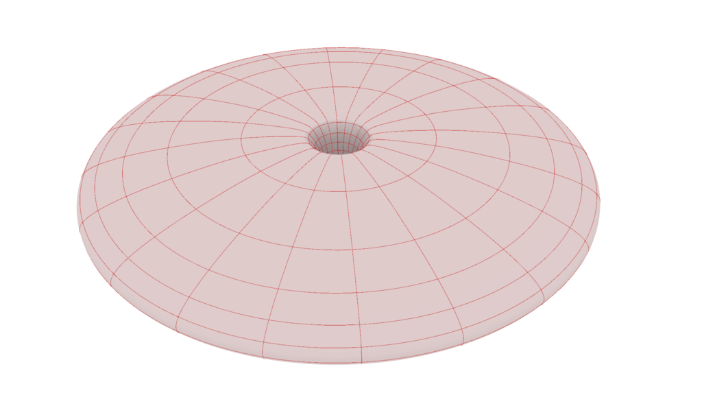
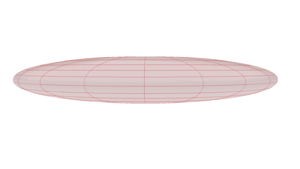
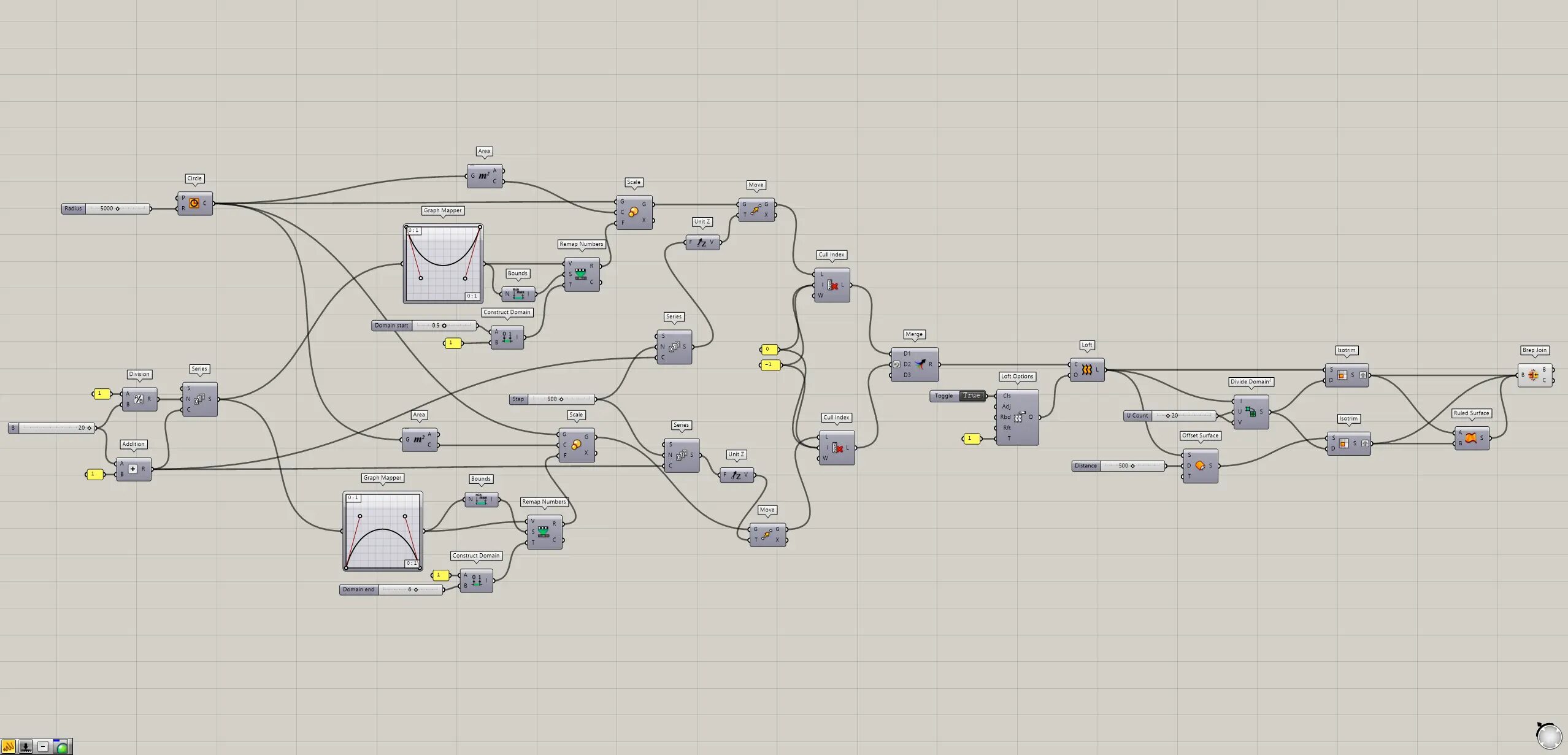
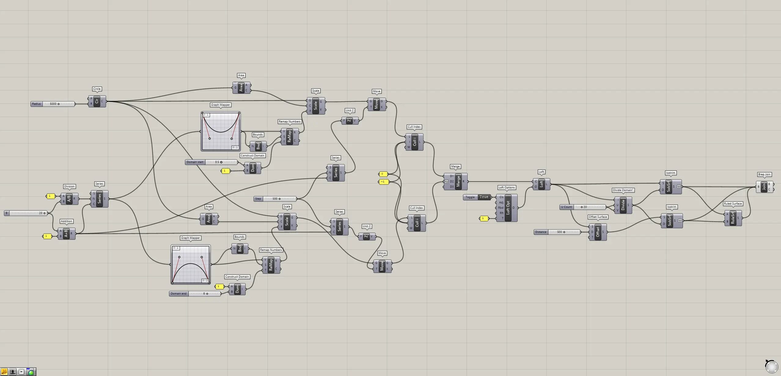
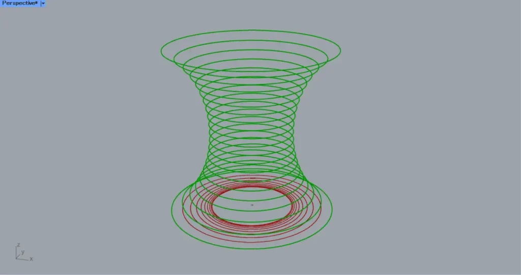
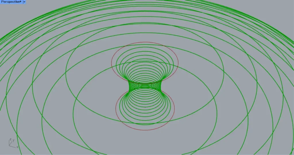
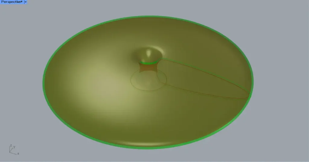
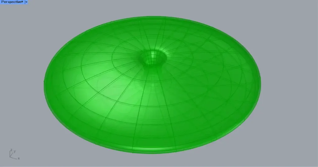
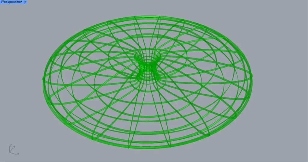
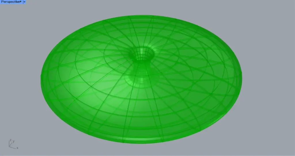
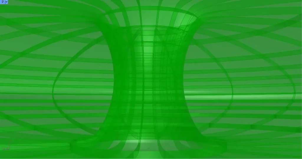
The top four images are from Grasshopper.
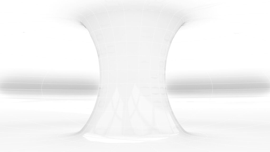
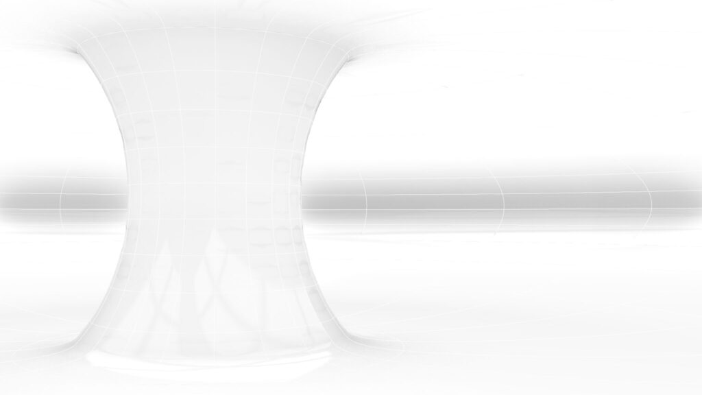
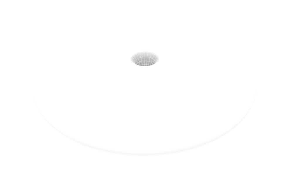

The top four images show the exported image on Rhinoceros.
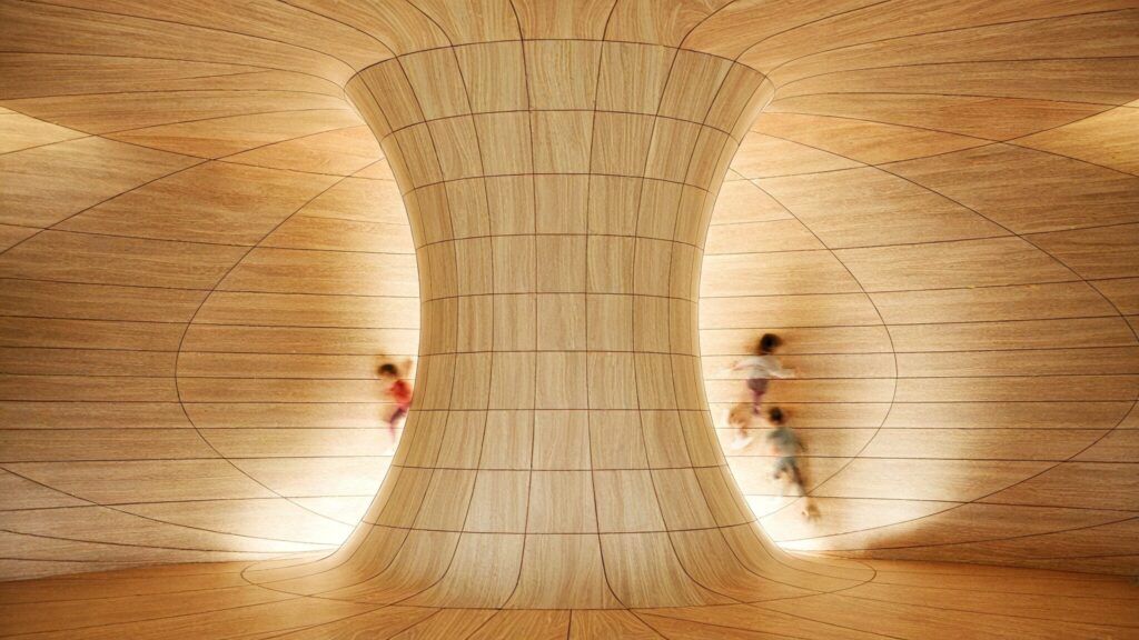
The image above shows the final rendering.
Click here to download the Grasshopper file
Please refer to the Terms of Use regarding the use of downloadable data.
Grasshopper recipe
①Circle ②Area ③Division ④Series ⑤Addition ⑥Graph Mapper ⑧Bounds ⑨Construct Domain ⑩Remap Numbers ⑪Scale ⑫Unit Z ⑬Move ⑭Cull Index ⑮Merge ⑯Boolean Toggle ⑰Loft ⑱Loft Options ⑲Offset Surface ⑳Divide Domain² ㉑Isotrim ㉒Ruled Surface ㉓Brep Join
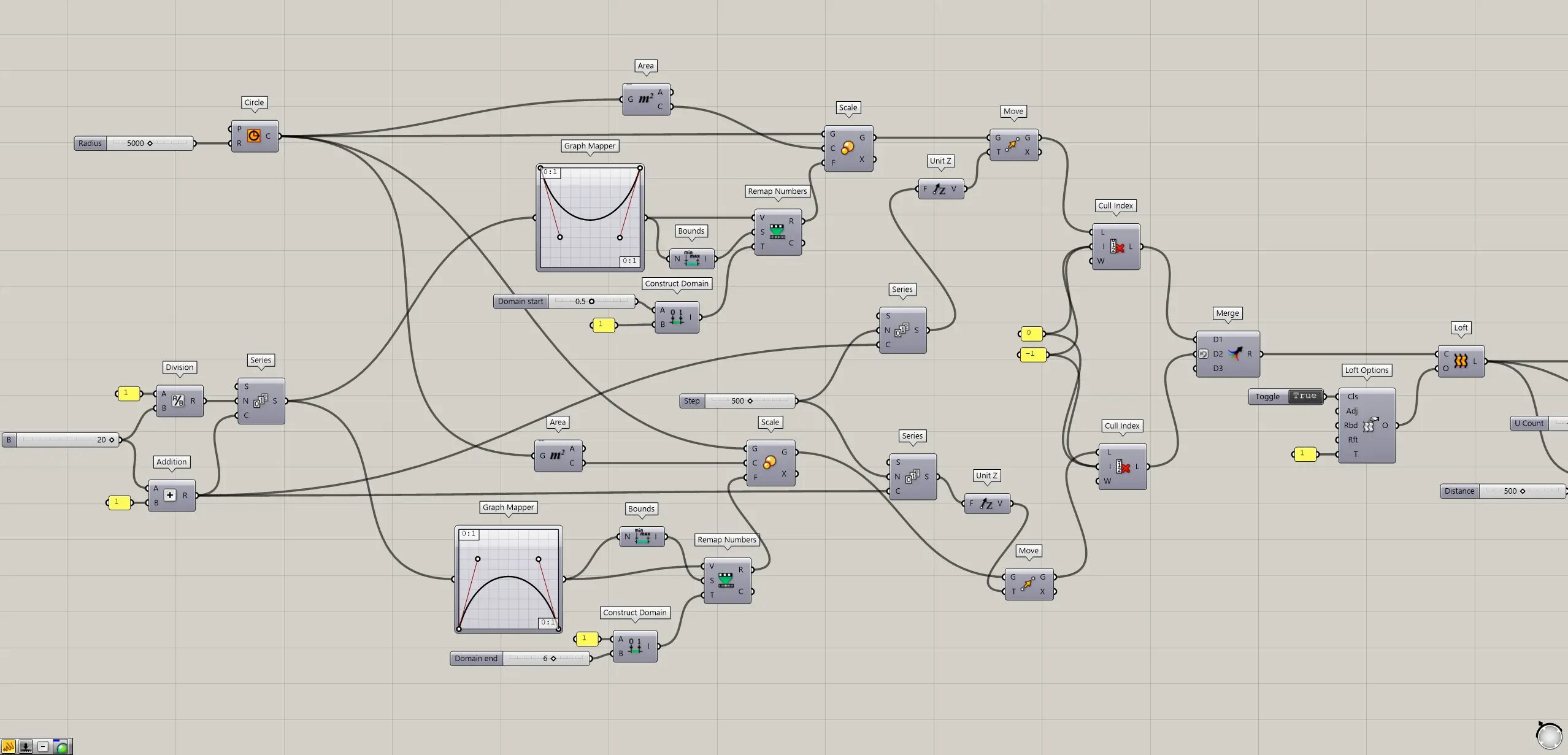
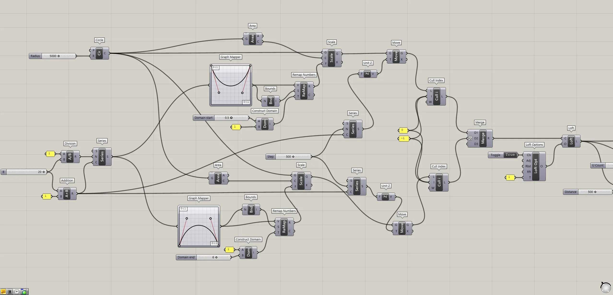
Change the scale of multiple circles
First, create multiple circles, each with a different scale.
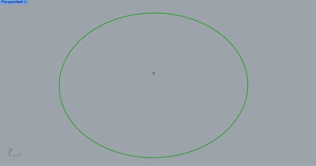
Connect a radius value to a Circle(R).
In this case, 5000 is input.
Then, as shown in the image above, line data for a circle with a radius of 5000 is created.
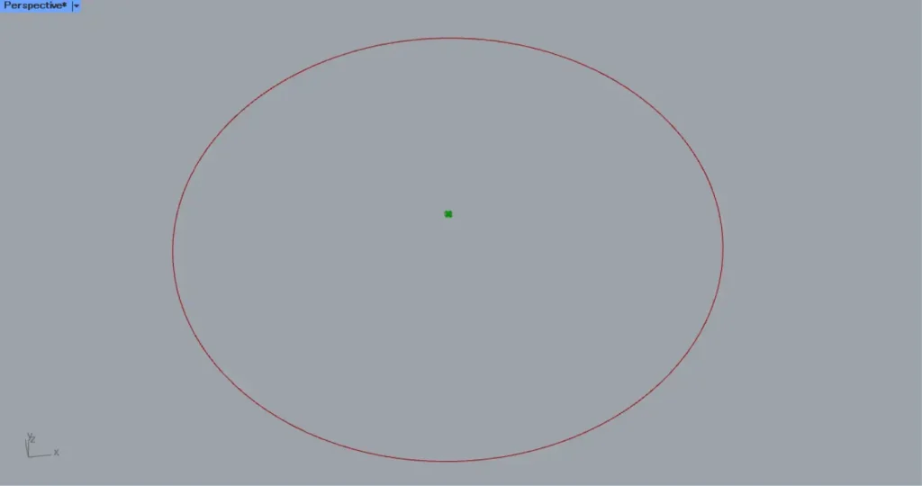
Then, connect the Circle to an Area.
Then you can get the center point of the circle, as shown in the image above.
Next, we will create numbers that change the scale.
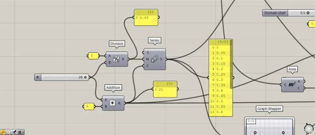
Connect a number that is 1 less than the number of circles to be created to Division(B).
In this case, 20 is input.
In addition, connect the 1 value to the Division(A).
Then the number 1 ÷ 20 = 0.05 is output.
Then connect the 20 to an Addition(A).
In addition, connect 1 the Addition(B).
Then 20+1=21 is output.
This value is the number of circles.
Then, connect the Division to a Series(N).
In addition, connect the Addition to the Series(C).
Then 21 numbers are created, each increasing by 0.05 from 0.
This number will be the X-axis number for the next graph.
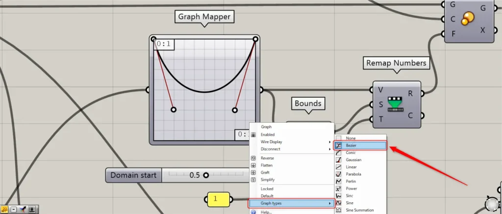
Then, connect the Series to a Graph Mapper.
At this time, right-click the Graph Mapper and set it to “Bezier” from “Graph types”.
Then, the Graph Mapper outputs the Y-axis value corresponding to the input X-axis value.
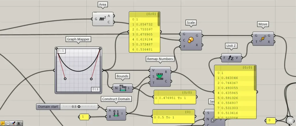
The Graph Mapper is then connected to a Bounds.
Then, a numerical range created from the minimum and maximum values of the numerical values output from the Graph Mapper is output.
Then, connect any multiplier value to a Construct Domain(A).
In this case, 0.5 is input.
Further, connect 1 to the Construct Domain(B).
Then, a numerical value range of 0.5 to 1 is created.
Then, connect the Graph Mapper to a Remap Numbers(V).
Then, connect the Bounds to the Remap Numbers(S).
Then, connect the Construct Domain to the Remap Numbers(T).
Then, the numerical value output from the Graph Mapper is converted in the range of 0.5~1.
Then, connect the Remap Numbers to a Scale(F).
Connect the Area(C) to the Scale(C).
Then, connect the Circle to the Scale(G).
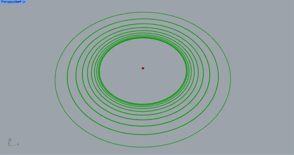
As shown in the image above, the scale of each circle has changed.
Now we can change the scale of multiple circles.
Move each circle directly upward
Next, each circle is moved directly upward.
Connect the Addition to a Series(C).
Furthermore, the numerical value of the interval to be moved directly upward is connected to the Series(N).
This creates 21 numbers that increase from 0 to 500 in increments of 500.
Then, connect Series to Unit Z.
Unit Z is then connected to a Move(T).
Then, connect the Scale(G) to the Move(G).
Then, as shown in the image above, each circle could be moved directly upward.
Create multiple circles on the outside
Next, we create the outer multiple circles.
Since most of this content overlaps with the previous programming content from Circle to Move, detailed explanations will be omitted.
Only the different parts are explained below.
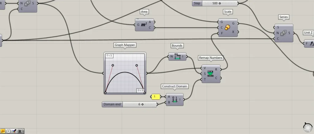
As shown in the image above, the shape of the Graph Madpper should be flipped up and down with respect to the first one.
Input 1 to the Construct Domain(A).
Also, input 6 to the Construct Domain(B).
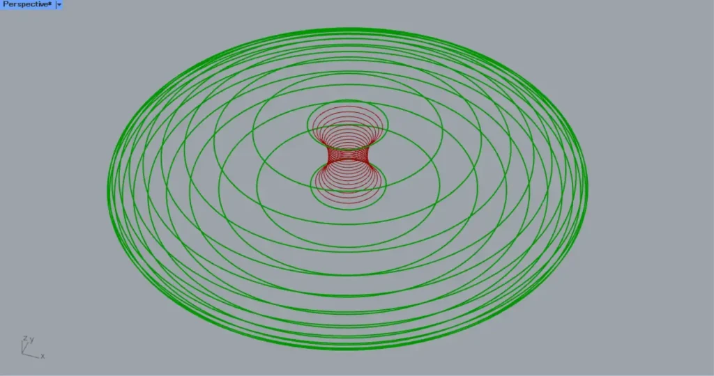
Then, multiple outer circles were created, as shown in the image above
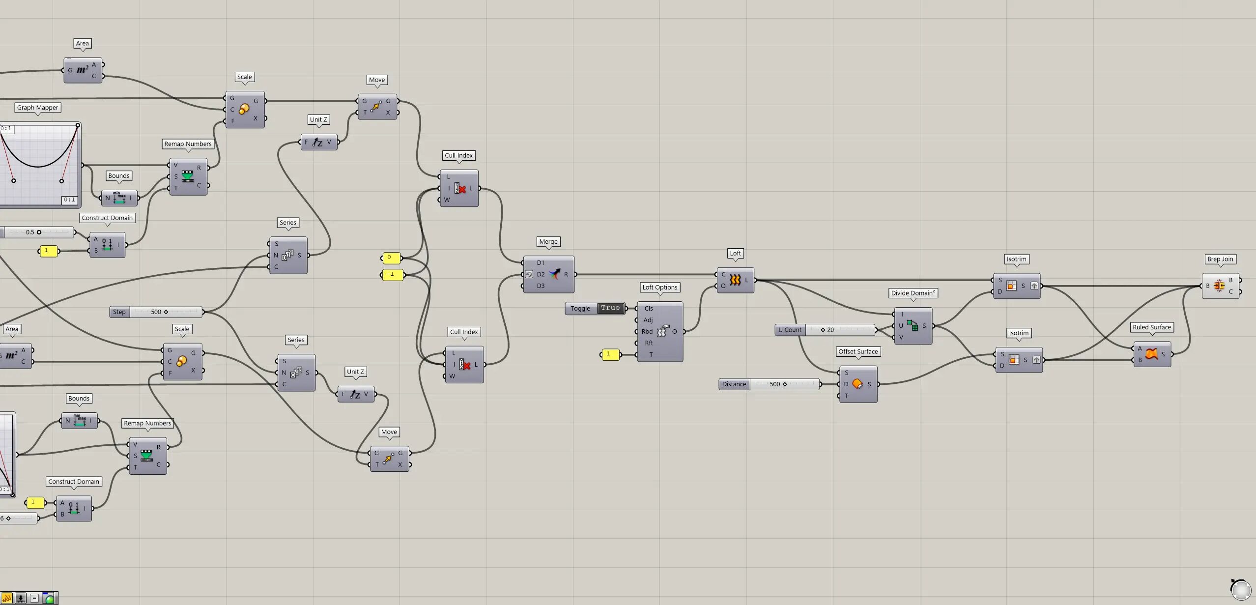
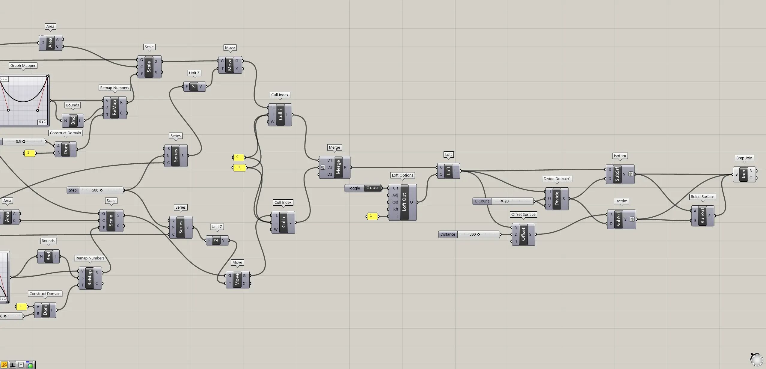
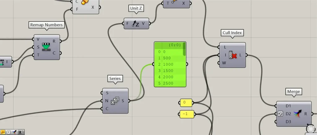
Create surfaces that connect the circles
Next, create surfaces that connect the circles.
Place two Cull Index.
Connect the the two Move(G) to the Cull Index(L).
Connect 0 and -1 to the Cull Index(I).
Then, as shown in the image above, only the first and last of the multiple circles were deleted.
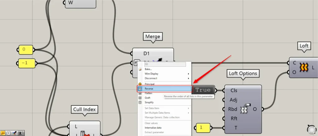
Then connect the two Cull Index to Merge.
At this time, right-click on the Cull Index(D2) and set it to Reverse.
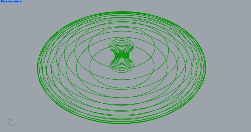
Then, as shown in the image above, the line data of the circles were combined.
Then, connect Merge to a Loft(C).
Then, connect a Loft Options to the Loft(O).
Then, connect the True information to the Loft Options(Cls).
In this case, the True information is created with the Boolean Toggle.
This closes the surface.
In addition, connect 1 to the the Loft Options(T).
This will set the setting to Loose and allow the circle line data to connect smoothly.
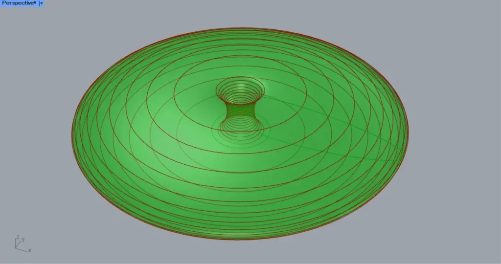
This creates a surface similar to the image above.
This will set the setting to Loose and allow the circle line data to connect smoothly.
This creates a surface similar to the image above.
You have now created a surface that connects the circles.
Thickness
Finally, add thickness.
Connect Loft to a Offset Surface(S).
In addition, connect the value to be offset to the Offset Surface(D).
In this case, 500 is input.
The surface is then offset, as shown in the image above.
However, the surface must be divided because it will not be thick enough as it is.
Connect Loft to a Divide Domain²(I).
In addition, connect the value of the number of divisions to the Divide Domain²(U and V).
In this case, 20 is input to both.
Then connect the Divide Domain² to two Isotrim(D).
Then connect the Loft to the first Isotrim(S).
Connect the Offset Surface to the second Isotrim(S).
The surface is divided as shown in the image above.
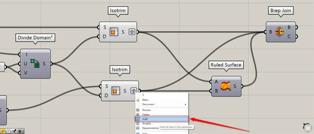
At this point, right-click on the two Isotrim(right S) and set them to Graft.
The two Isotrim are then connected to a Ruled Surface.
This creates surfaces that connect the borders of the previous and next surfaces.
The two Isotrim and Ruled Surface are then connected to a Brep Join.
The three surfaces are then joined.
This completes the process.
That is all for this time.

Comment