
![[Grasshopper]MultiPipeを使った内装デザイン方法[データも配布]](https://iarchway.com/wp-content/uploads/2025/02/eyecatch_web-3.jpg)
This article describes how to design interior using MultiPipe.
The Grasshopper file used in this project is also available for download.
Video
Model Images
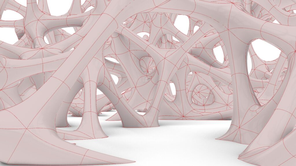
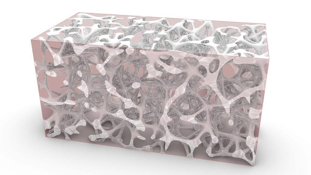
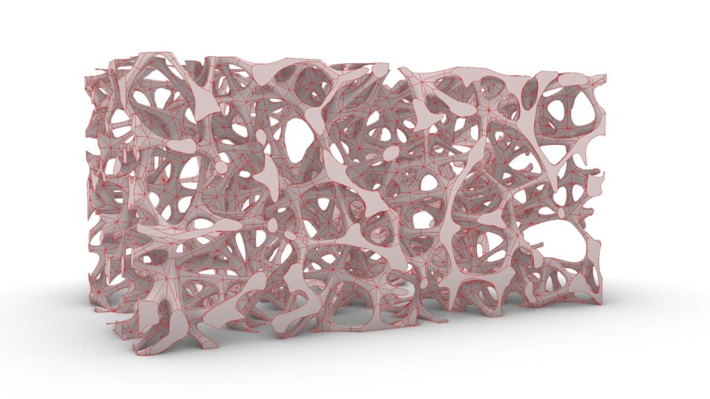
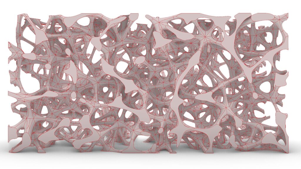
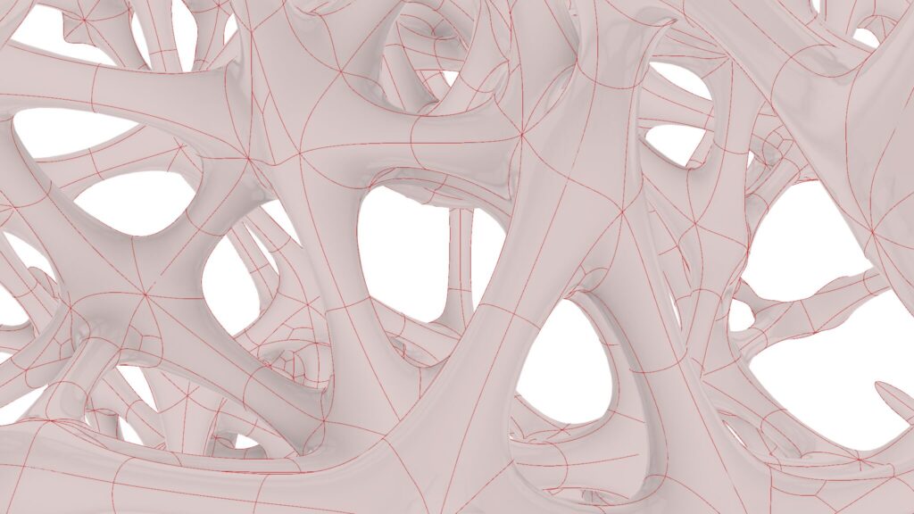
The top five images are from Grasshopper.
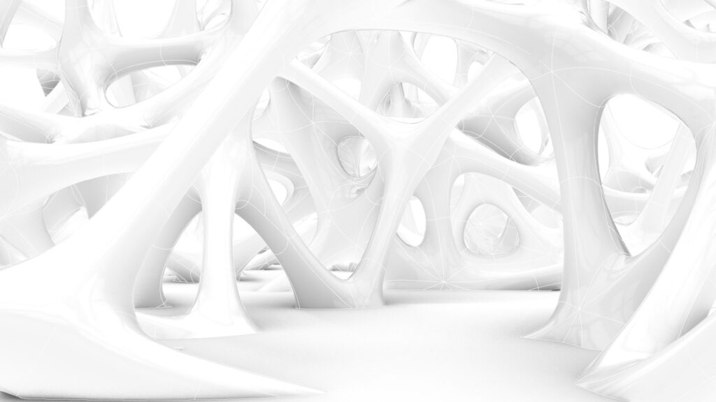

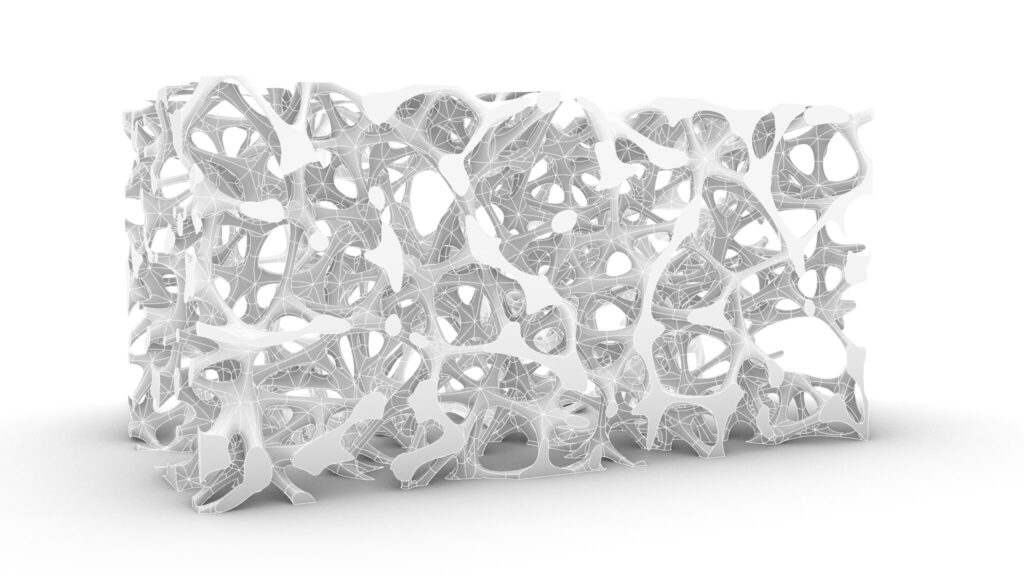
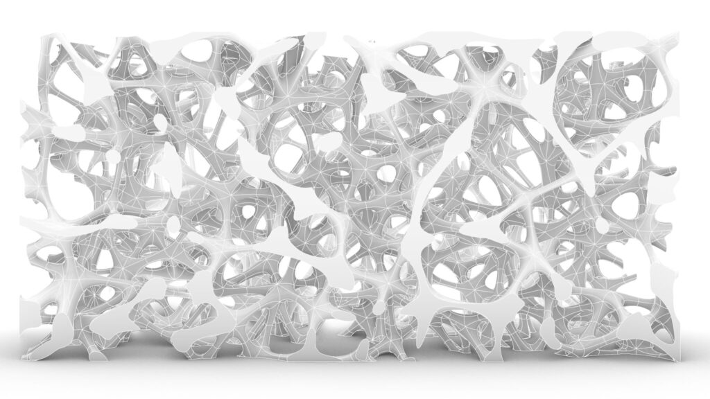
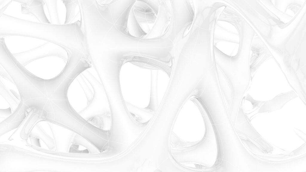
The top five images show the model exported on Rhinoceros.
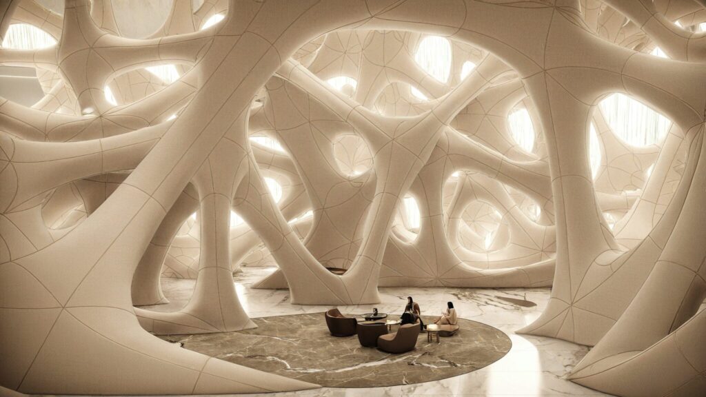
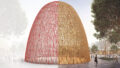
The image above shows the final rendering.
Click here to download the Grasshopper file
Please refer to the Terms of Use regarding the use of downloadable data.
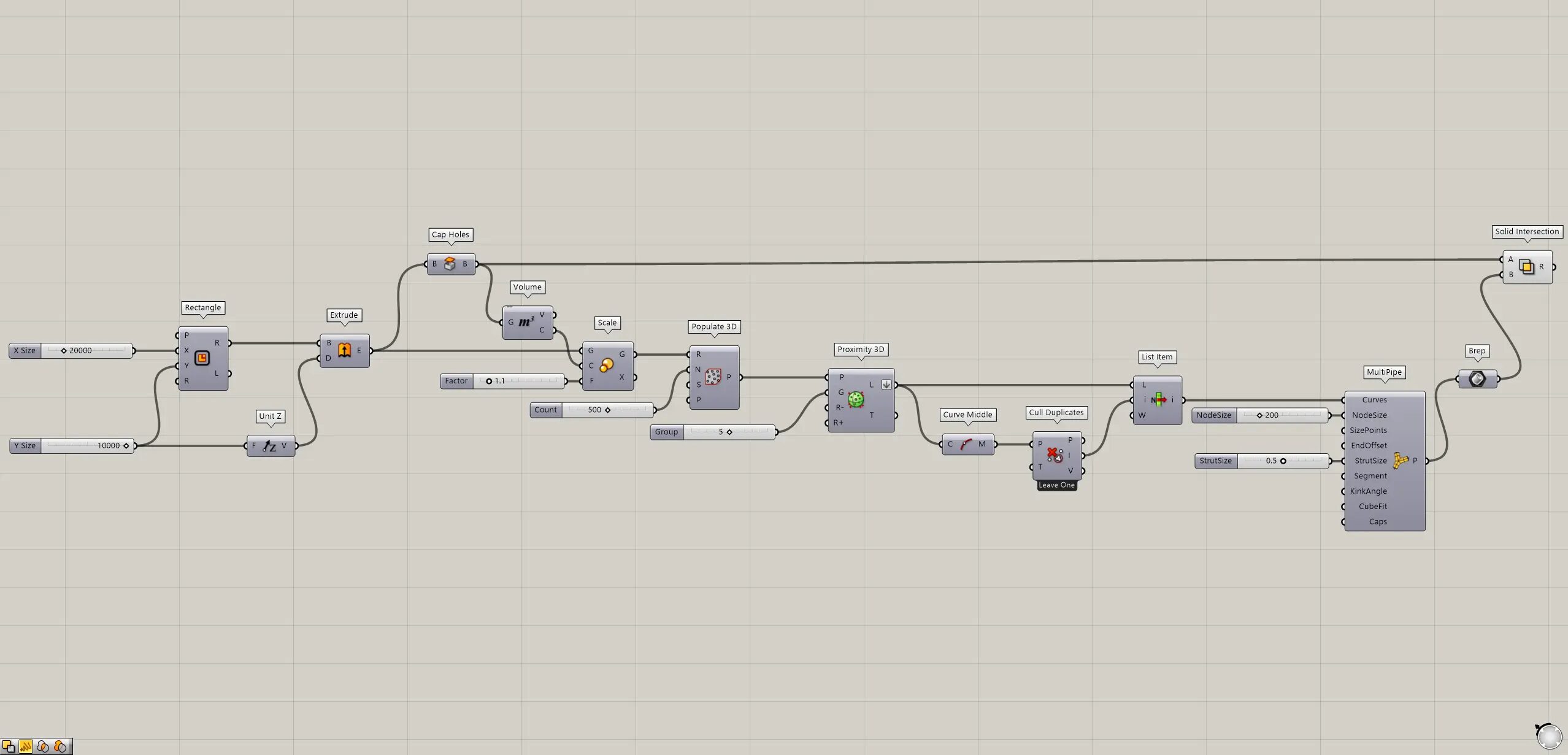
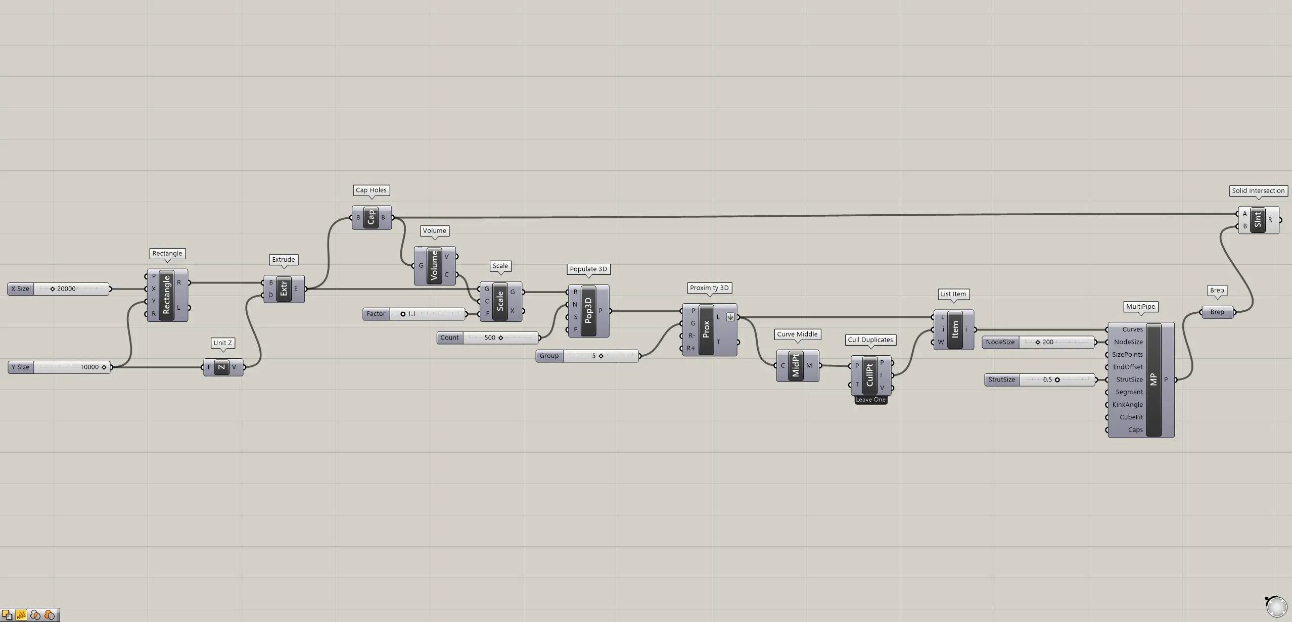
Grasshopper recipe
①Rectangle ②Unit Z ③Extrude ④Cap Holes ⑤Volume ⑥Scale ⑦Populate 3D ⑧Proximity 3D ⑨Curve Middle ⑩Cull Duplicates ⑪List Item ⑫MultiPipe ⑬Brep ⑭Solid Intersection
Creae random points within a box
First, Creae random points within a box.
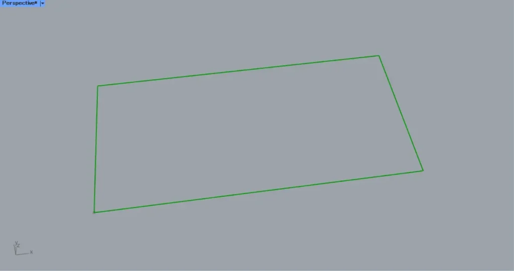
Connect the numerical values for the side lengths of the rectangle lines to a Rectangle(X and Y).
This time, 20000 and 10000 are input to the X and Y respectively.
Then a 20000 x 10000 rectangular line data was created, as shown in the image above.
Then connect the height values to a Unit Z.
This time, we connect the 10000 value from earlier.
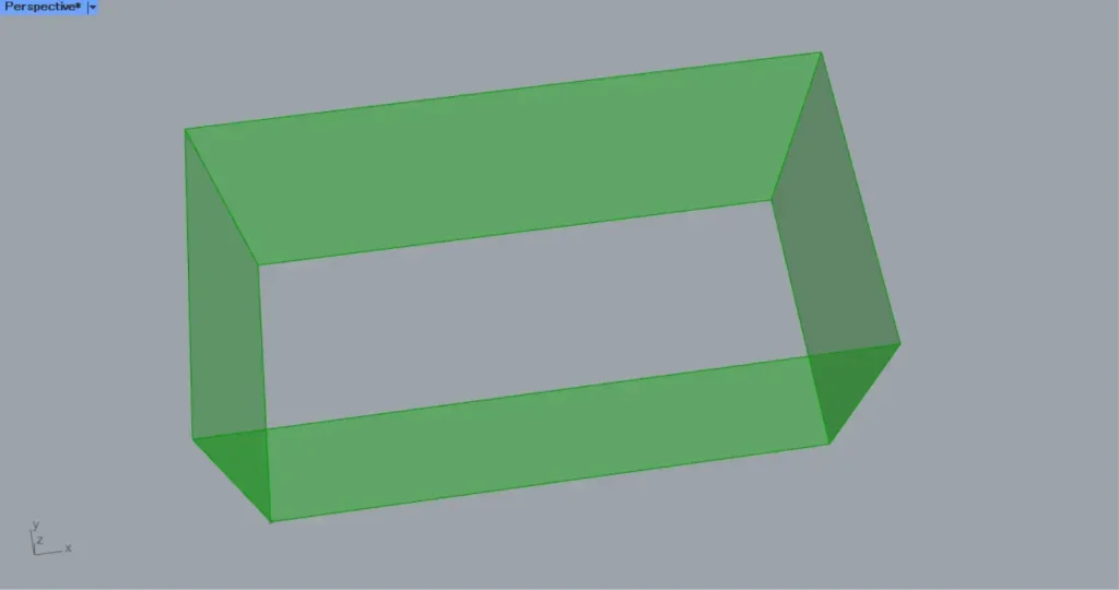
Then connect the Unit Z to an Extrude(D).
Then the rectangular line data is pushed straight up, as shown in the image above.
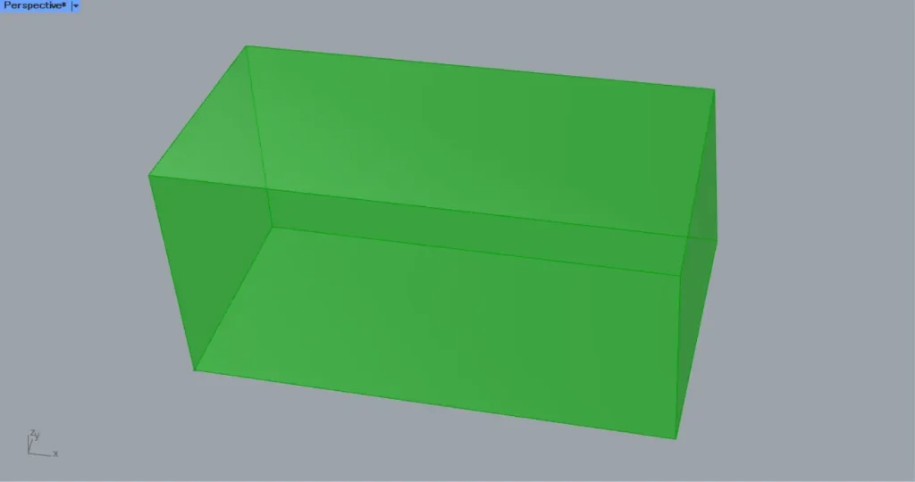
Then connect the Extrude to Cap Holes.
Then The hole is plugged up, as shown in the image above.
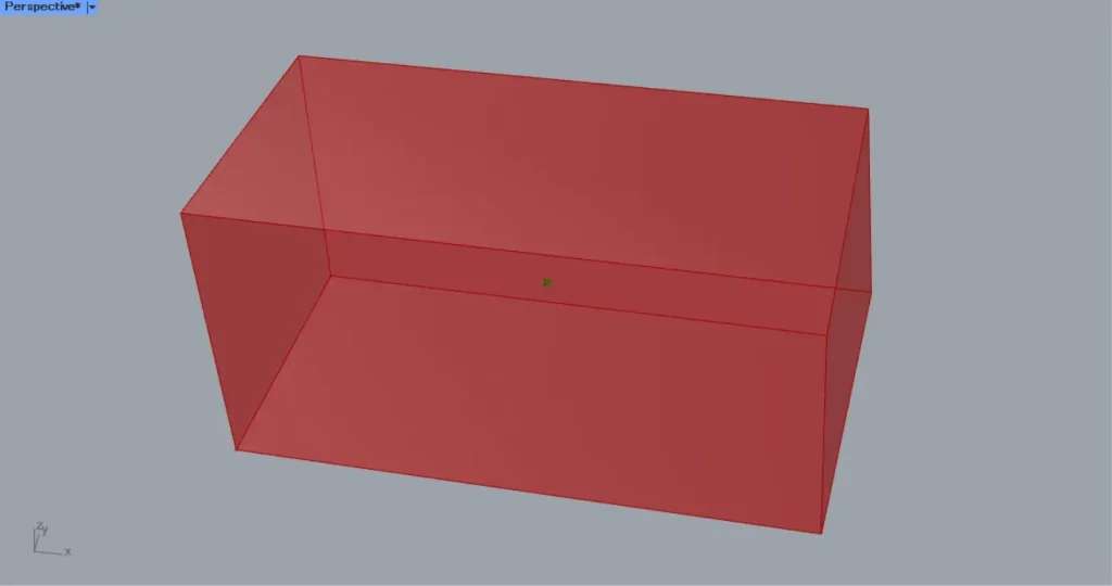
Then connect the Cap Holes to a Volume.
Then The center point of the box is obtained, as shown in the image above.
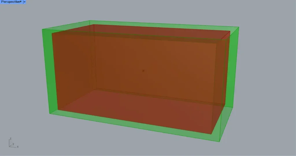
Then connect the Volume(C) to a Scale(C).
In addition, connect the Extrude to the Scale(G).
Furthermore, connect the magnification value to the Scale(F).
In this case, 1.1 is input.
Then a rectangle 1.1 times larger is created, as shown in the image above.
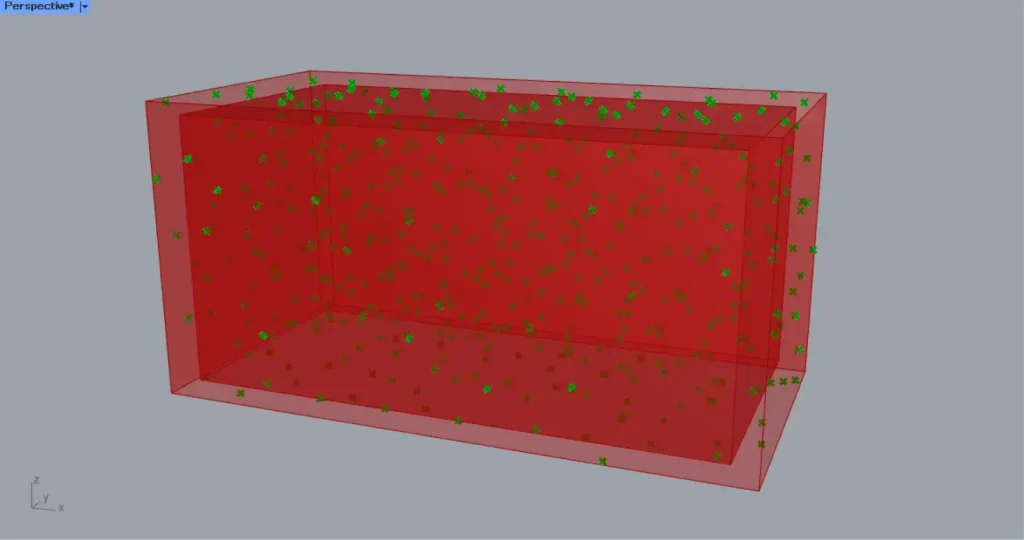
Then connect the Scale(G) to a Populate 3D(R).
Furthermore, connect the number of points to the Populate 3D(N).
In this case, 500 is input.
Then 500 random points are created within the rescaled box, as shown in the image above.
If you want to change the position of random points, connect any randomness-changing seed value number to the Populate 3D(S).
Create lines connecting the points.
Next, create lines connecting the points.
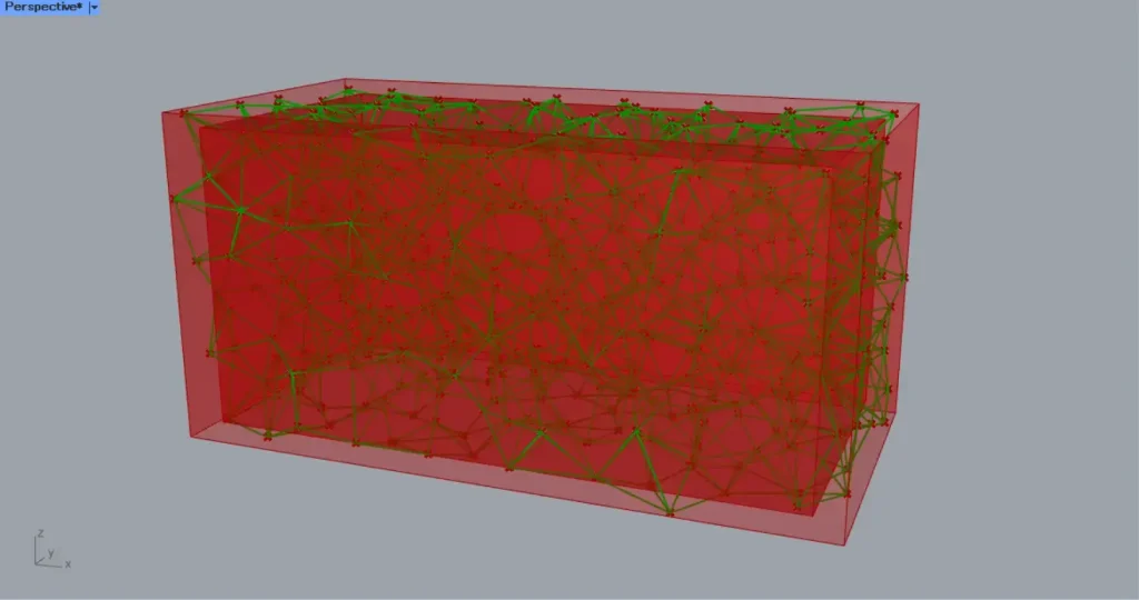
Connect Populate 3D to a Proximity 3D(P).
In addition, connect the number of points that connect to other points to the Proximity 3D.
This time, 5 is input.
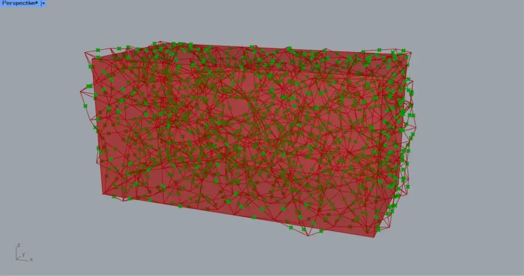
Then lines are created connecting the 5 points around each point, as shown in the image above.
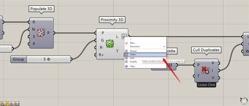
In this case, right click on the Proximity 3D(L) and set it to Flatten.
Next, we remove the duplicate lines.
Then connect the Proximity 3D(L) to a Curve Middle.
As you can see in the image above, the midpoints of each line are obtained.
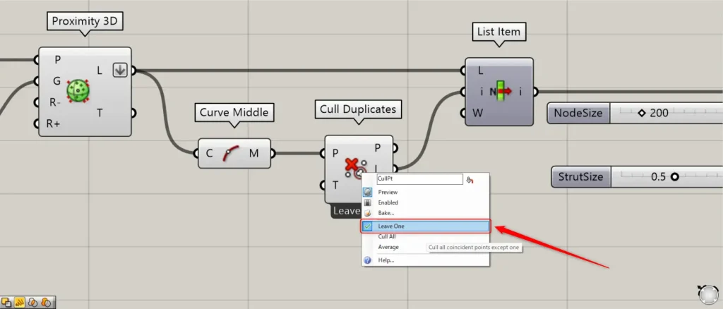
Then connect Curve Middle to a Cull Duplicates(P).
At this time, right click on the Cull Duplicates and set it to Leave One.
Then, you can delete the duplicate midpoints and leave one.
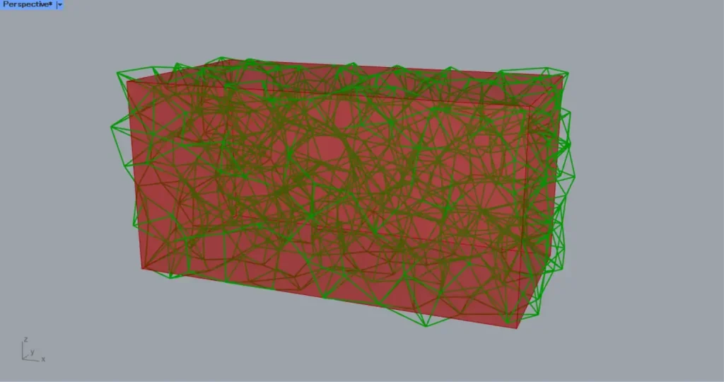
Then connect the Cull Duplicates(I) to a List Item(i).
Furthermore, connect the Proximity 3D(L) to the List Item(L).
Then you can get only the lines that correspond to the remaining points.
Get the intersection of the pipe and the box
Finally, get the intersection of the pipe and the box.
Connect List Item to a MultiPipe(Curves).
Connect the node size value to the MultiPipe(NodeSize).
In this case, input 200.
In addition, input a numerical value for the magnification factor of the size between nodes, between 0~1.
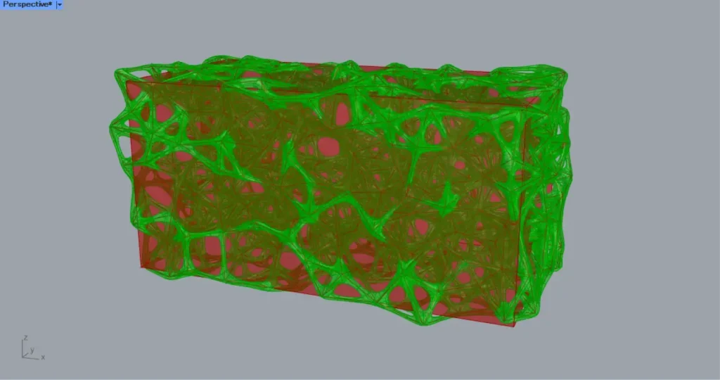
This time, 0.5 is input.
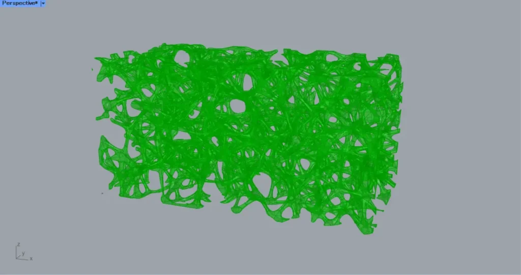
Then a pipe is created with the middle of the node half the size of the node, as shown in the image above.
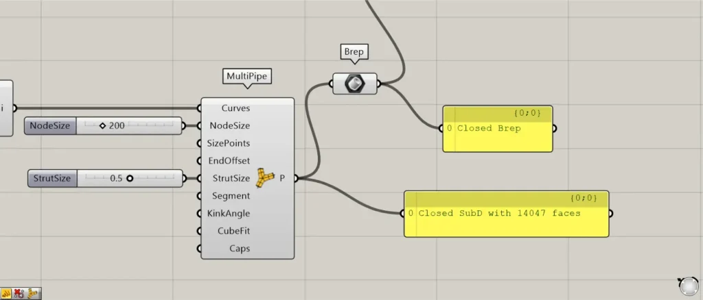
Then connect the MultiPipe to a Brep.
The SubD model MultiPipe is then converted to a Brep model.
This allows for Boolean addition and subtraction.
Then connect the Brep and the Cap Holes to a Solid Intersection.
Then we get only the intersection of the box and the pipe, as shown in the image above.
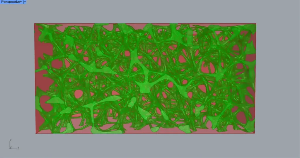
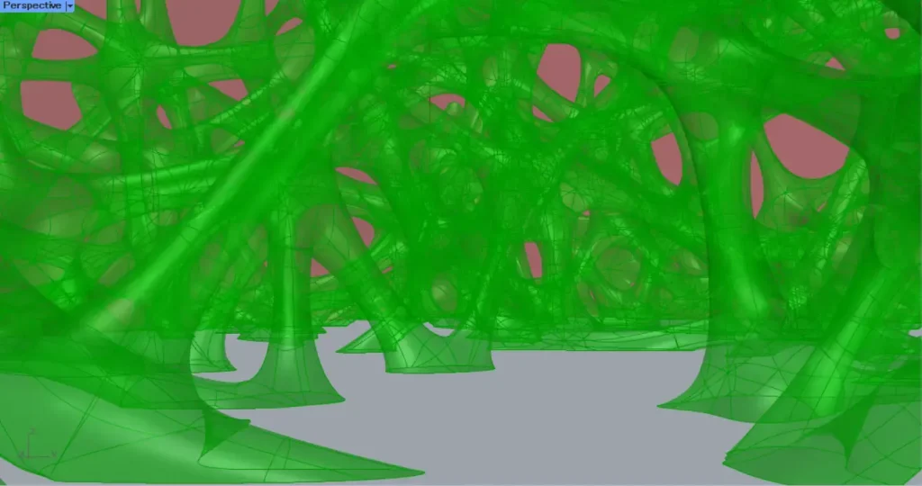
This completes the process.
That’s all for this issue.


Comment