
![[Grasshopper]ねじれる位置が変わっていくルーバーの作成方法](https://iarchway.com/wp-content/uploads/2025/01/eyecatch2_web-7.jpg)
In this article, we will learn how to create Louvers in varying positions of twisting in Grasshopper.
Video
Model Images
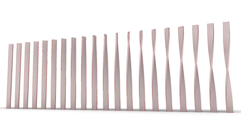
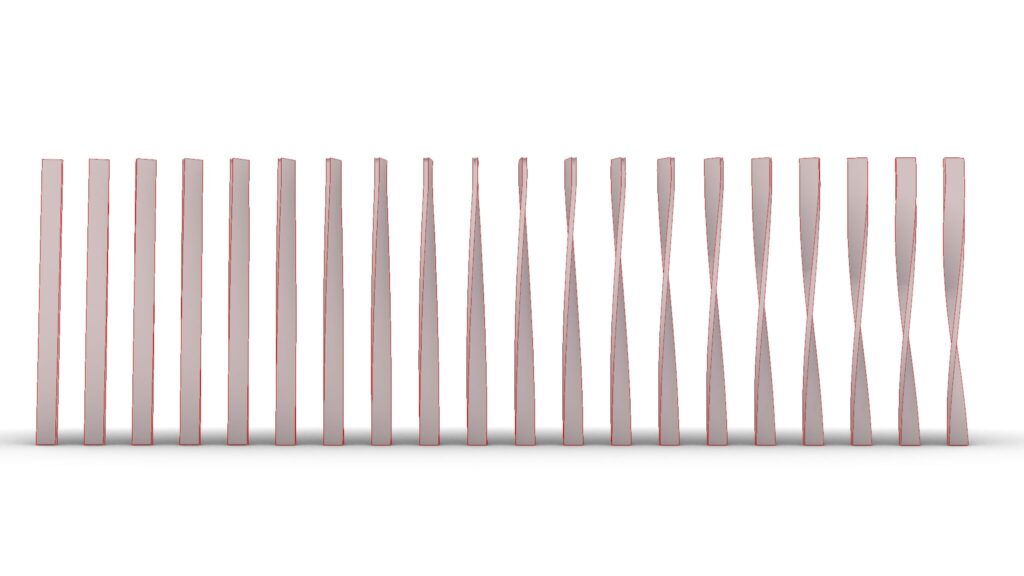
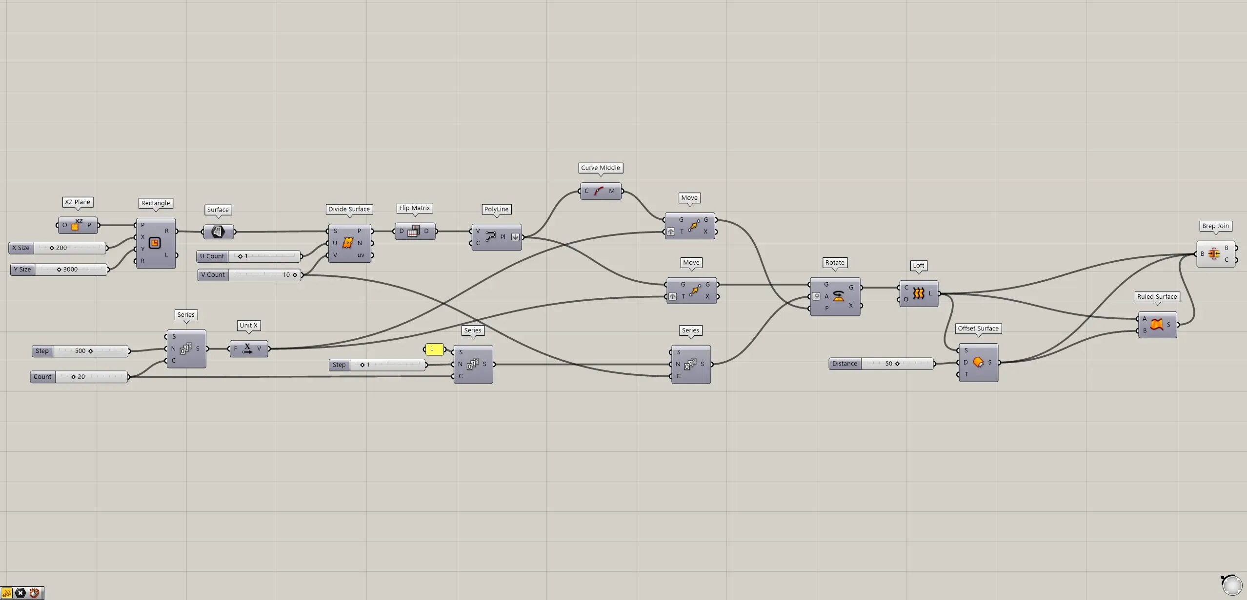
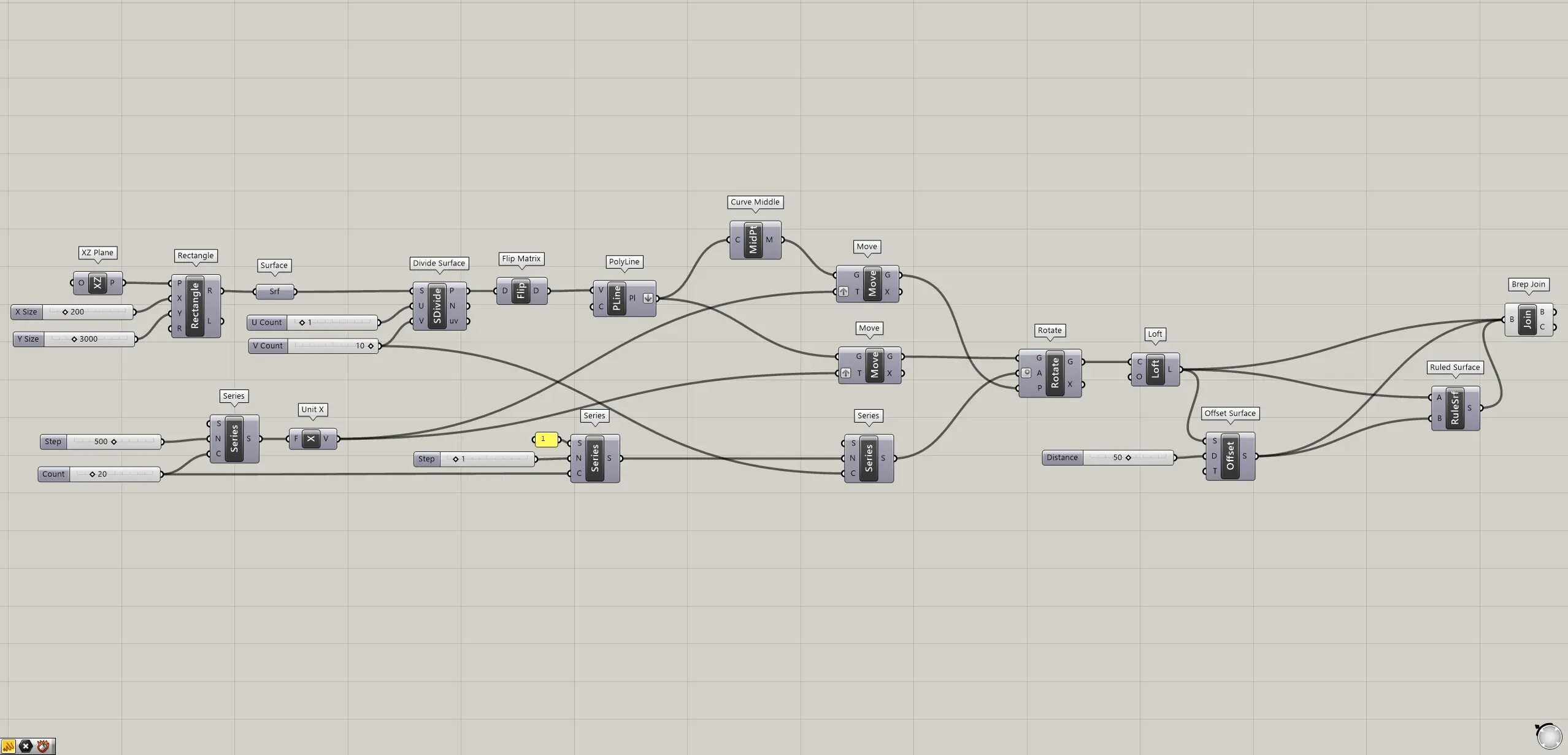
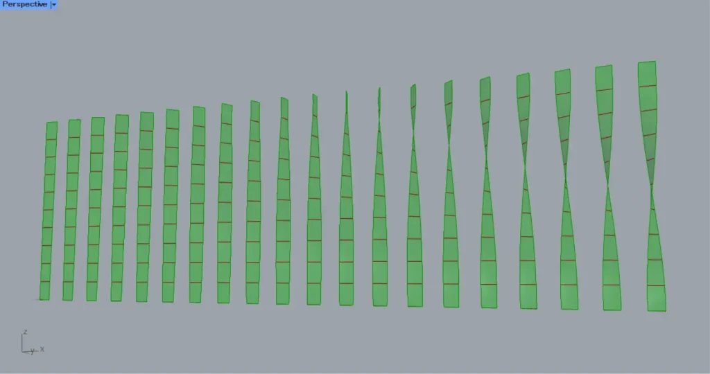
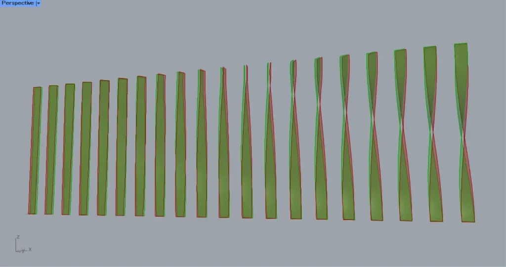
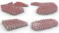
The top two images are from Grasshopper.
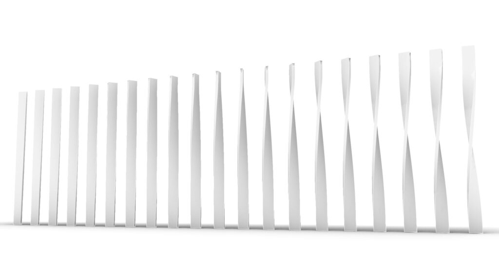
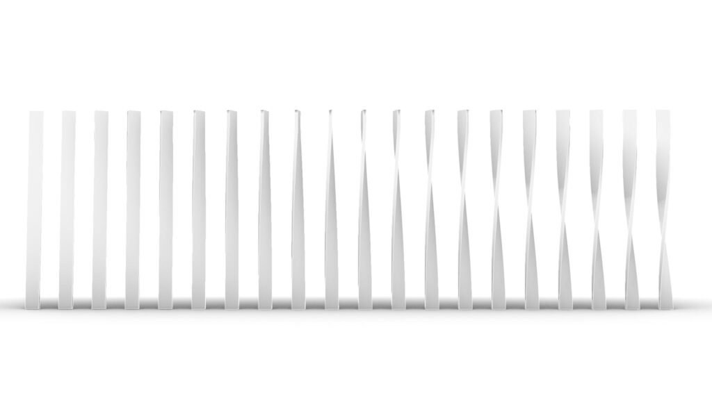
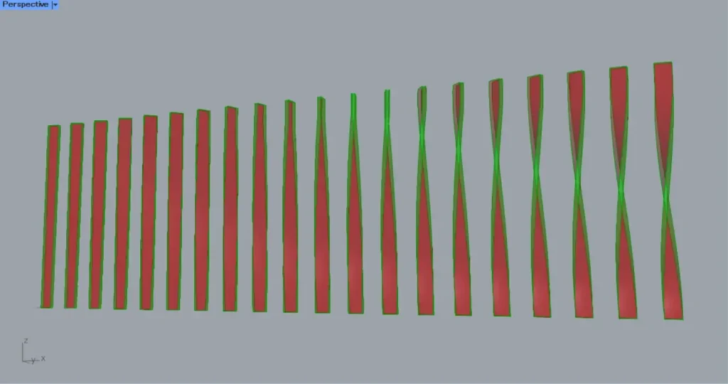
The top two images show the model exported on Rhinoceros.

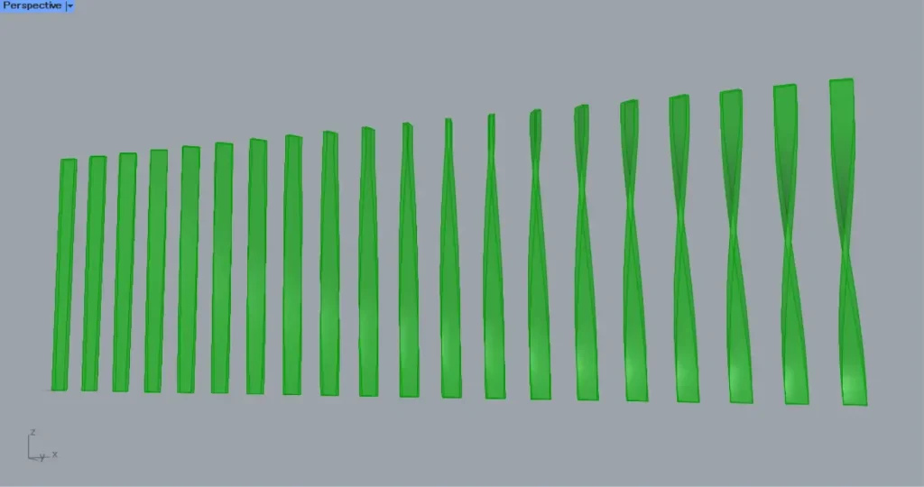
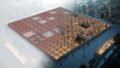
The image above shows the final rendering.
Click here to download the Grasshopper file
Please refer to the Terms of Use regarding the use of downloadable data.
Grasshopper recipe
①XZ Plane ②Rectangle ③Surface ④Divide Curve ⑤Flip Matrix ⑥PolyLine ⑦Curve Middle ⑧Series ⑨Unit X ⑩Move ⑪Rotate ⑫Loft ⑬Offset Surface ⑭Ruled Surface ⑮Brep Join
Create a rectangular surface and get the division points
First, we will Create a rectangular surface and get the division points.
First, prepare a XZ Plane.
Then a plane is created that can be made from the X and Z directions.
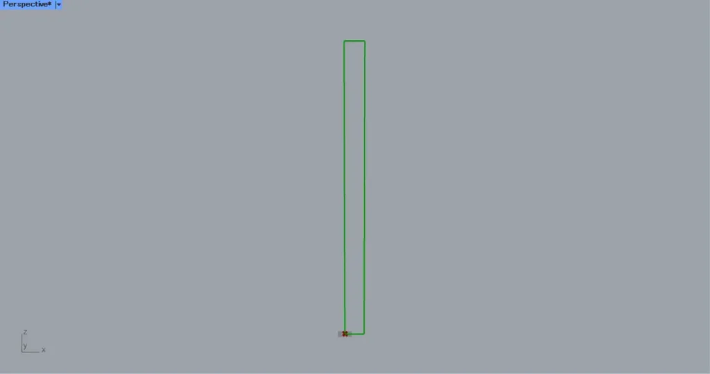
Then connect the XZ Plane to a Rectangle(P).
In addition, enter the numeric values for the side lengths in the Rectangle(X and Y).
In this case, the values of 200 and 3000 are entered in the X and Y, respectively.
Then a rectangular line is created, as shown in the image above.
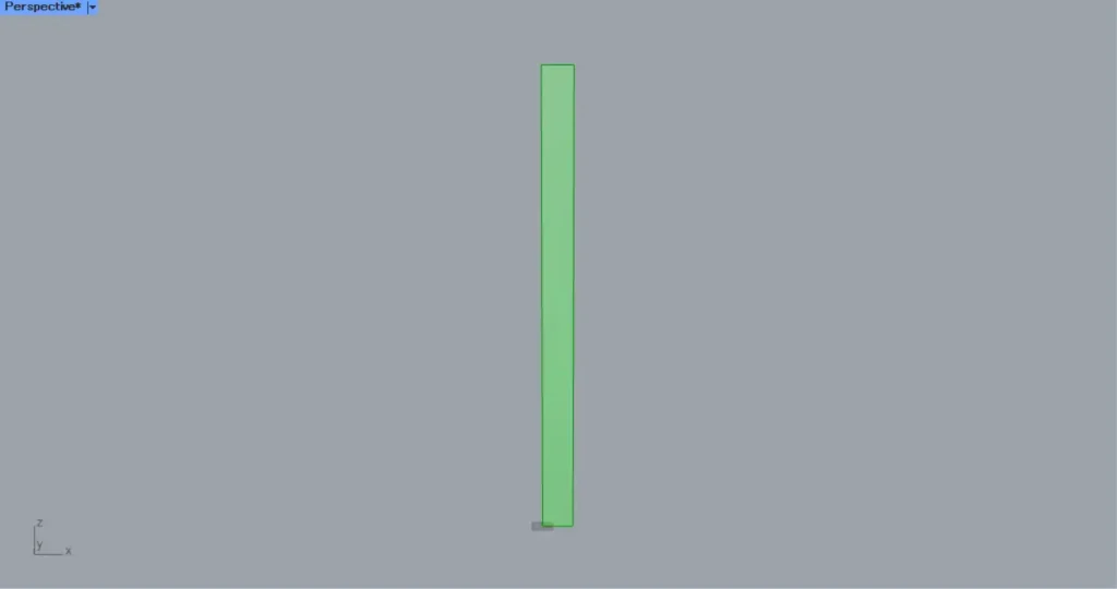
Then connect the Rectangle(R) to a Surface.
Then a surface is created from the rectangular line, as shown in the image above.
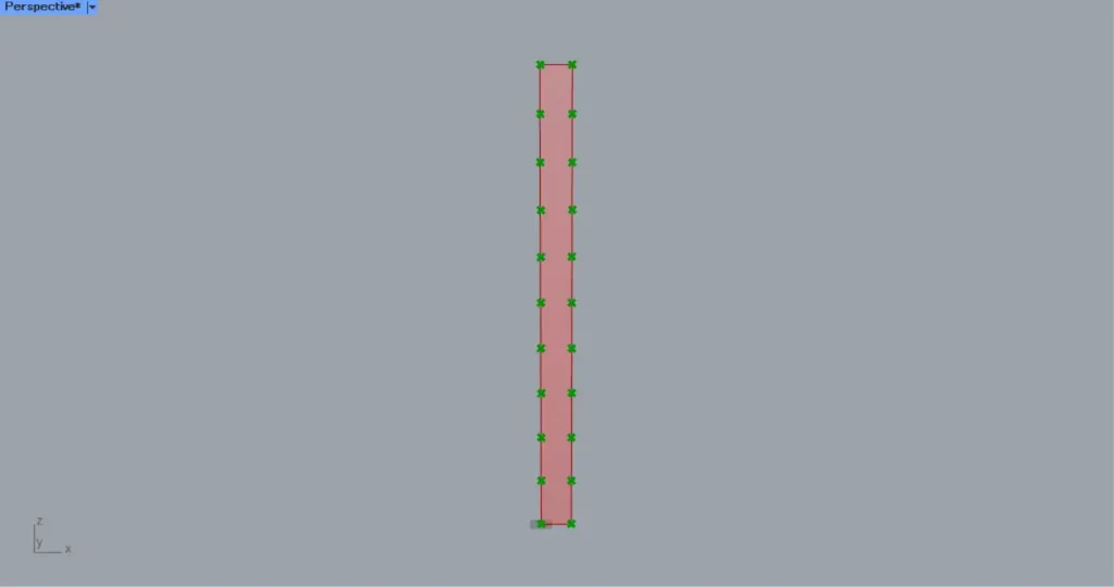
Then connect the Surface to a Divide Surface(S).
In addition, enter numerical values for the number of surface divisions in the U and V terminals of the Divide Surface.
In this case, the numbers 1 and 10 are entered in the U and V, respectively.
Then division points are created at the positions where the surface is divided into 1 x 10 pieces, as shown in the image above.
Move and copy the straight lines connecting the division points and the midpoints
Next, we will Move and copy the straight lines connecting the division points and the midpoints.
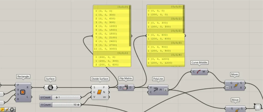
Connect the Divide Surface(P) to a Flip Matrix.
Then the rows and columns of data are swapped, and the 10 vertical point data in one set (branch) are combined into one set of 2 horizontal data.
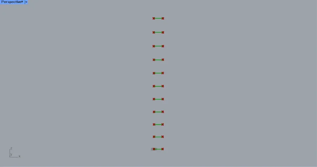
Then connect the Flip Matrix to a PolyLine(V).
Then horizontal straight lines are created, as shown in the image above.
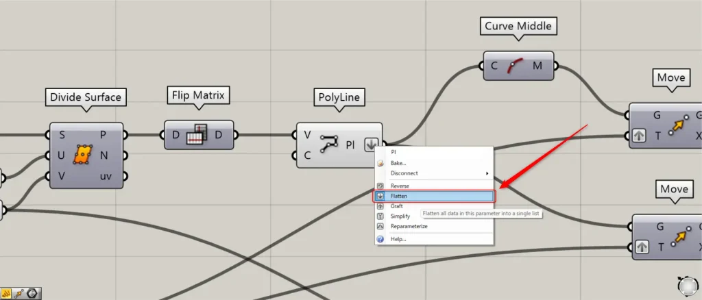
At this point, right click on the PolyLine(Pl) and set Flatten.
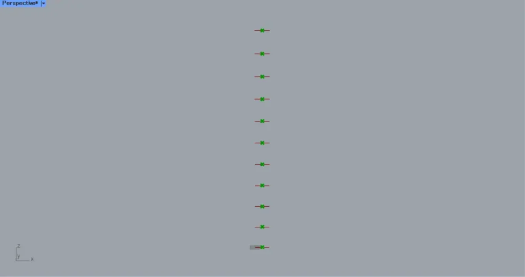
Then connect the PolyLine(Pl) to a Curve Middle.
Then you can get the midpoint of each line, as shown in the image above.
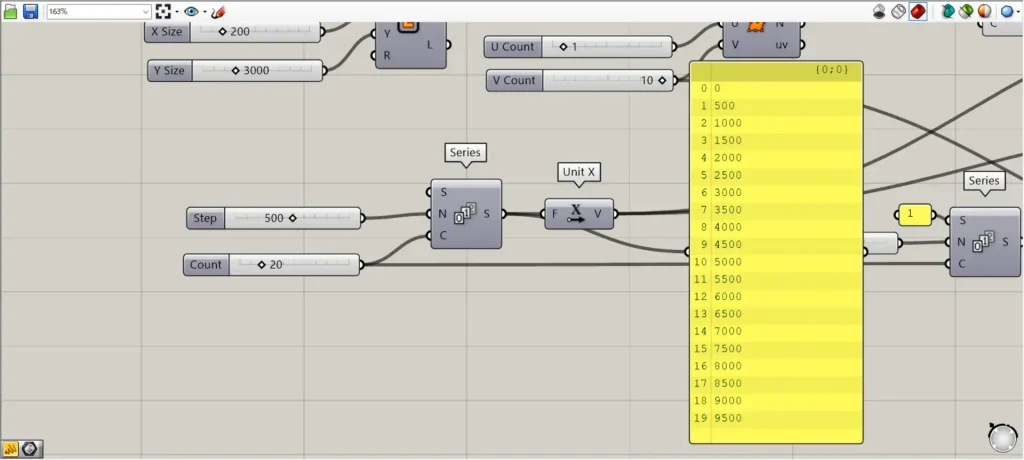
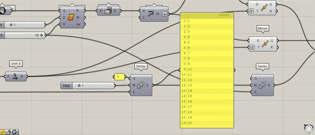
Next, we will create the values to be moved and copied in the X direction.
Enter the numerical value of the interval in a Series(N).
In this case, 500 is input.
Furthermore, connect the number of pieces to be copied to the Series(C).
In this case, 20 is entered.
Then 20 numbers will be created, each increasing by 500 from 0, as shown in the image above.
Then connect the Series to an Unit X.
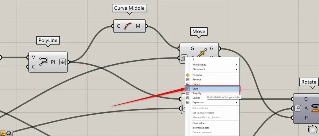
Then connect the Unit X to two Move(T).
At this point, right click on the two Move(T) and set them to Graft.
Then connect the Curve Middle to the the first Move(G).
In addition, connect the PolyLine to the second Move(G).
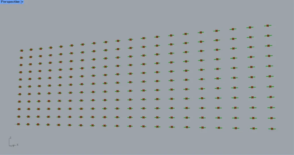
Then we are able to move-copy the straight lines and the midpoints, as shown in the image above.
Create louvers that each rotate at different angles
Finally, we will create louvers that rotate at different angles.
Connect the 20 used in the previous Series to a Series(C).
In addition, connect 1 to the Series(S).
Furthermore, connect the increasing angle value of each louver rotation to the Series(N).
This time, 1 is entered.
Then 20 numbers will be created, each increasing by 1 from 1.
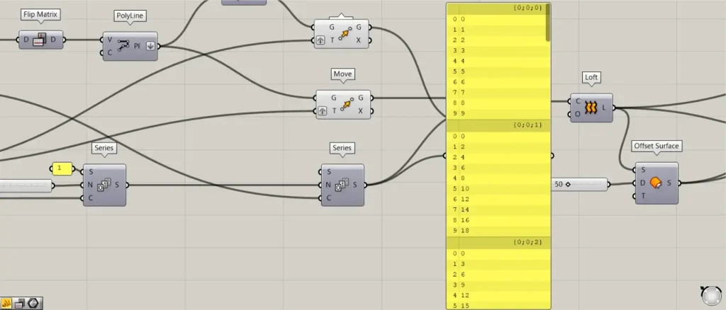
Then connect the Series to a new Series(N).
Furthermore, connect the 10 used in the Divide Curve to the Series(C).
Then each set (branch) will create numbers that increase by a constant value from 0.
This increases so that the first louver rotates by 1 degree, the second by 2 degrees, and the third by 3 degrees.
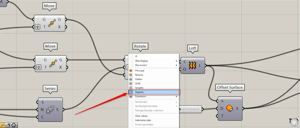
Then connect the Series to Rotate(A).
At this point, right click on the Rotate(A) and set it to Degrees.
In addition, connect the Move(G) of the Curve Middle to the Rotate(P).
In addition, connect the Move(G) of the PolyLine to the Rotate(G).
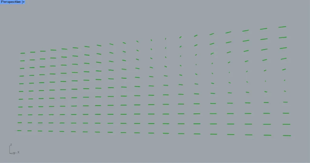
Then the lines are rotated, as shown in the image above.
Then connect the Rotate(G) to a Loft(C).
This will create surfaces that connect vertical lines, as shown in the image above.
Then connect the Loft to a Offset Surface(S).
Furthermore, connect the number to be offset to the Offset Surface(D).
In this case, 50 is entered.
Then the surface are offset, as shown in the image above.
Then the Loft and the Offset Surface are connected to a Ruled Surface.
Then surface are created connecting the two surfaces, as shown in the image above.
Then connect the Loft, the Offset Surface and the Ruled Surface to a Brep Join.
Then each surface has been combined, as shown in the image above.
This completes the process.
That is all.

Comment